
Background
In the previous few posts we discussed the fundamentals of Uniform Linear Arrays (ULAs), Beamforming, Multiuser Detection and Massive MIMO ([1], [2], [3], [4]). Now we turn our attention to more complicated array structures such as rectangular, triangular and circular. We still assume each element of the array to have an isotropic or omni-directional (in the plane of the array) radiation pattern. The mathematical models for more complicated radiation patterns are an extension of the what is developed here.
Square and Rectangular Arrays
In this post we consider a square array which is a special case of rectangular array. We build up from the most basic case of a 2 x 2 array and derive the equation of the resultant signal, which is simply the summation of the individual signals received at the four array elements. Later on we give the MATLAB code which can be used to plot the radiation pattern of any size rectangular array.
Derivation of the Array Pattern
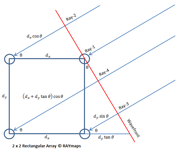
Lets consider a plane wave impinging upon a 2 x 2 receive array. The source is considered to be in the far field of the receive array making the plane wave assumption to be realistic. The equations for the received signal at the four array elements are given below. Please note that since the combined signal only depends upon the relative phase of the four components we assume the phase at the wavefront (red line in the figure below) to be zero. Also note that we have assumed that dx=dy=d.
r1=1
r2=e-j2πdcos(θ)/λ
r3=e-j2πdsin(θ)/λ
r4=e-j2πd(cos(θ)+sin(θ))/λ
The resultant signal can then be written as:
rt=r1+r2+r3+r4
In general for an N x M array the resultant signal can be written as:
rt=∑∑ e-j2πd(ncos(θ)+msin(θ))/λ
When the array is not square i.e. the separation along the x and y axes is not the same we have:
rt=∑∑ e-j2π(ndxcos(θ)+mdysin(θ))/λ
The range of n and m is 0 to N-1 and 0 to M-1 respectively.
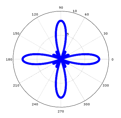
8 x 8 Square Array Radiation Pattern
MATLAB Code for a Rectangular Array
%%%%%%%%%%%%%%%%%%%%%%%%%%%%%%%%%%%%
% SIMPLE RECTANGULAR ARRRAY
% WITH N x M ELEMENTS
% COPYRIGHT RAYMAPS (C) 2018
%%%%%%%%%%%%%%%%%%%%%%%%%%%%%%%%%%%%
clear all
close all

f=1e9;
c=3e8;
l=c/f;
dx=l/3;
dy=l/3;
theta=0:pi/1800:2*pi;
N=8;
M=8;

r=0;
for n=1:N
  for m=1:M
    r=r+exp(-i*2*pi*(dx*(n-1)*cos(theta)+dy*(m-1)*sin(theta))/l);
  end
end

polar(theta,abs(r),'bo-')
title ('Gain of a Uniform Linear Array')
Discussion of Simulation Results
In the above code we have assumed a carrier frequency of 1 GHz which gives us a wavelength of 0.3 meter. The element separation along the x and y axis is assumed to be 0.1 meter (lambda/3). The total number of elements is 8 x 8 = 64. The maximum gain obtained is equal to 8 on the linear scale or 9 dB on the logarithmic scale. The radiation pattern has four peaks which does not make this array structure to be of much practical use. More complex array structures resulting in more desirable radiation patterns will be discussed in future posts.
Note:
Please note that we have simplified the problem significantly by assuming an omnidirectional pattern of the array elements and plotting the composite radiation pattern only in the plane of the array. In reality the array elements do not always have an omnidirectional radiation pattern (one popular antenna that does have an omnidirectional pattern is a dipole) and we have to plot the 3D pattern of the array (or cuts along different planes) to get a better understanding of the characteristics such as Half Power Beamwidth, First Null Beamwidth and Side Lobe Level etc. More on this later.
Author: Yasir
More than 25 years of experience in various organizations in Pakistan, the USA, and Europe. Worked with the Mobile and Portable Radio Group (MPRG) of Virginia Tech and Qualcomm USA and was one of the first researchers to propose Space Time Block Codes for eight transmit antennas. Had the opportunity to work with world renowned wireless experts such as Dr. Ted Rappaport, and Dr. Jeffrey H. Reed. Have published a book “Recipes for Communication and Signal Processing” through Springer Nature.
9 thoughts on “Fundamentals of a Rectangular Array – Mathematical Model and Code”
Hello,
If i want to steer the array to a certain location, how do you change the 2D array:
r=r+exp(-i*2*pi*(dx*(n-1)*cos(theta)+dy*(m-1)*sin(theta))/l);
Thank you!
Hi Michael,
You would have to look at the 3D radiation pattern to understand this. Please have a look at the post on Circular Array where I talk about 3D radiation patterns.
YA
How did you derive the signal equation for a rectangular array from the equations on your reference web-page :
http://www.antenna-theory.com/arrays/weights/twoDuniform.php
Hi Chaim,
Thanks for reaching out. Please look at the four references, at the start of the post, to understand the basics. If you still do not understand something please let us know.
YA
Thank you for sharing the above information.
how could a rectangular array of rectangular aperture antennas be calculated?
is there a way to use the array factor of the rectangular array in conjunction with the expected radiation intensity of the rectangular waveguide?
Respectfully,
Cosmic
If the elements are identical (antenna array made up of all the same type of antennas), and have the same physical orientation (all point or face the same direction), then the radiation (or reception) pattern for an antenna array is simply the Array Factor multiplied by the radiation pattern. This concept is known as pattern multiplication.
Reference: http://www.antenna-theory.com/arrays/arrayfactor.php
thank you very much sir..its really very helpful.
If possible can you post the detailed mathematical equation for linear, circular and rectangular array.
I think I have already posted the equations for rectangular and circular array. Square array is just a special case of rectangular array. Hope this helps…