Open Signal Coverage Maps for Pakistan

Open Signal is a mobile application that collects the data about your wireless network (2G/3G/4G) and generates coverage maps and host of other reports. The data is collected in the background while the user is busy in his daily routines. But data can also be collected on the request of the user. This is much better than drive testing since the data is collected in real life scenarios and on thousands of different devices that are in use. The app works while the user is indoor or outdoor, at rest or in motion, on land or on water, at sea […]

Read more

Eclipse

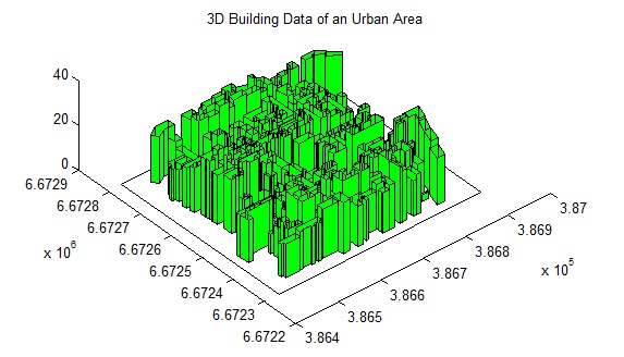
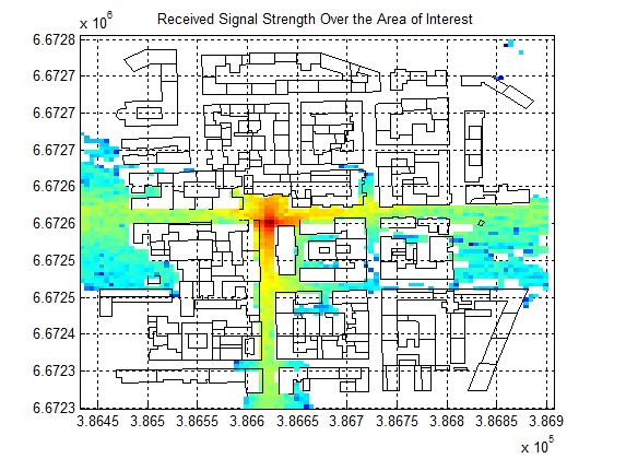
Eclipse 1.0 – A Paradigm Shift in RF Planning NEW: Simulation of a Moving Transmitter (such as a car) NEW: Simulation of a Moving Transmitter (such as a pedestrian) Radio frequency planning is an essential component of network planning, roll-out, up-gradation, expansion etc. Several methods can be adopted for this from something as simple as free space models, empirical path loss models to the significantly more complicated, time consuming and expensive drive testing. Drive testing gives very accurate results but these results can be rendered useless by changing the position of an antenna or the tilt or transmit power of […]

Read more

Android Apps

1. Rx Signal Meter Received signal strength calculation is required by RF engineers working in the field. This application provides an easy to use interface to calculate the received signal strength. Input parameters include the transmit power, transmit antenna gain, receive antenna gain, transmit receive separation and frequency of operation. Output is the received signal strength in dBm. https://play.google.com/store/apps/details?id=com.raymaps.path.loss 2. Rx Signal Pro A simple application that can be used to calculate the Received Signal Strength using one of the following six models. 1. Free Space Path Loss 2. Hata Model 3. COST-231 Model 4. ECC-33 Model 5. Ericsson Model 6. SUI […]

Read more

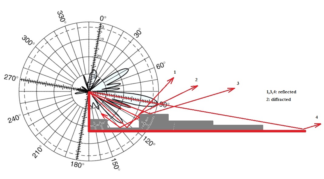
Antenna Radiation Pattern and Antenna Tilt

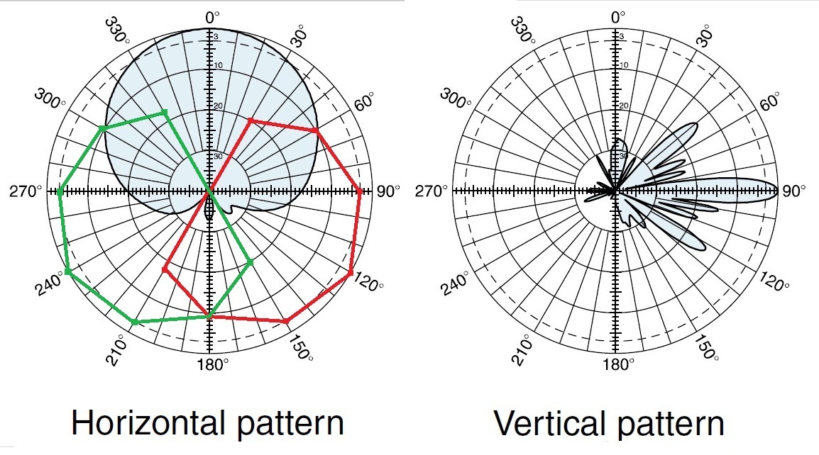
An introductory text in Communication Theory would tell you that antennas radiate uniformly in all directions and the power received at a given distance ‘d’ is proportional to 1/(d)^2. Such an antenna is called an isotropic radiator. However, real world antennas are not isotropic radiators. They transmit energy in only those directions where it is needed. The Gain of a antenna is defined as the ratio of the power transmitted (or received) in a given direction to the power transmitted in that direction by an isotropic source and is expressed in dBi. Although antenna Gain is a three dimensional quantity, […]

Read more

Base Station Antenna Tilt and Path Loss

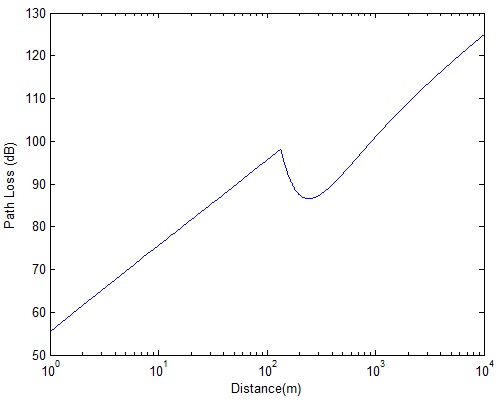
Path loss is basically the difference in transmit and receive powers of a wireless communication link. In a Free Space Line of Sight (LOS) channel the path loss is defined as: L=20*log10(4*pi*d/lambda) where ‘d’ is the transmit receive separation and ‘lambda’ is the wavelength. It is also possible to include the antenna gains in the link budget calculation to find the end to end path loss (cable and connector losses may also be factored in). Antenna gains are usually defined along a horizontal plane and vertical plane passing through the center of the antenna. The antenna gain can then be […]

Read more

Qualcomm In Muddy Waters In India

Remember Qualcomm CEO Paul Jacobs proudly claiming that his company had prevented WiMAX from getting a hold in India by acquiring BWA licenses in four regions of India. Well now Qualcomm is in a bit of bother as the Department of Telecommunication (DoT) in India has raised objections to the license application filed by Qualcomm. According to news circulating on the internet the DoT has objected to Qualcomm filing four separate applications through its nominee companies in the four regions (Delhi, Mumbai, Kerala and Haryana) it had won the licenses on June 12, 2010. Secondly the DoT has also objected […]

Read more

WiMAX Path Loss and Antenna Height

As discussed previously the SUI (Stanford University Interim) model can be used to calculate the path loss of a WiMAX link. The SUI model is given as: SUI Path Loss Equation It has five components: 1. The free space path loss (A) up to the reference distance of ‘do’. 2. Additional path loss for distance ‘d’ with path loss exponent ‘n’. 3. Additional path loss (Xf) for frequencies above 2000 MHz. 4. Path gain (Xh) for receive antenna heights greater than 2 m. 5. Shadowing factor (s). The most important factor in this equation is the distance dependent path loss. […]

Read more

LTE Path Loss at 700 MHz

In the previous post we had compared the path loss of LTE at 728 MHz and 1805 MHz in a free space line of sight channel. This is a very simplistic channel model which tells us that ratio of the received signal strengths at these frequencies can be simply found as: (f1/f2)^2=(1805/728)^2=6.15 That is the received signal strength at 728 MHz is 6.15 times higher than the received signal strength at 1805 MHz. Now let us consider a more realistic channel model known as the COST-231 model. According to this model the path loss (difference between the transmit power and […]

Read more

Propagation and In-Building Penetration at 700MHz

It is quite well known that wireless signals travel further at lower frequencies. This phenomenon has become particularly important in the context of LTE where a frequency band has been allocated at 700MHz. We would like to quantify the benefits that can be achieved by using this frequency band. Firstly we find the received signal power at 728 MHz (lowest downlink frequency) and at 3600 MHz (highest downlink frequency) in a free space line of sight channel. The transmit power is set to 1 W and omnidirectional antennas are considered at the transmitter and receiver. The received power for these […]

Read more