
The Electromagnetic Radiation from an antenna, particularly dipole antenna, has been studied in great detail. The mathematical framework proposed by Maxwell has stood the test of time and theoretical concepts have been verified through physical measurements. But the behavior of Electromagnetic (EM) waves close to the radiating antenna is not that well understood. This region that extends to about a wavelength from the antenna is called Near Field, as opposed to Far Field, which extends further out. The Near Field is further divided into Reactive Near Field and Radiative Near Field.
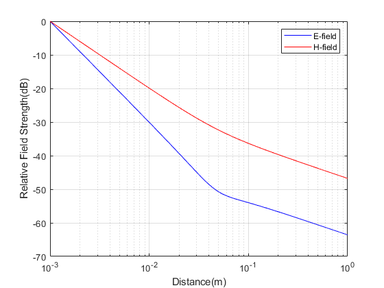
We know that in the Far Field the E-field, H-field and directional of propagation are all perpendicular to each other and E-field and H-field are in phase. The impedance of free space (given as ratio of E-field and H-field) in this region is equal to 377 ohms (120π ohms). But this is not the case in Near Field where E-field is much greater than H-field and these fields are not in phase. Furthermore the rate of decay of E-field and H-field is much higher in the Near Field.
Given below is the code that plots the E-field and H-field (normalized, so that rate of decay can be compared) in the three regions. It can be seen that there is no clear boundary defining the three regions; the fields and resulting impedance gradually change as the distance from the transmit antenna increases. In the far field both the E-field and H-field decay at 10dB/decade. In the region closest to the antenna E-field decays at 30dB/decade whereas H-field decays as 20dB decade.
%%%%%%%%%%%%%%%%%%%%%%%%%%%%%%%%%%%%%%%%%%%%%%%%%%%%
% E-field and H-field of a Small Dipole Antenna
% f is the frequency
% c is the speed of light
% lambda is the wavelength
% k is the wave number
% L is the length of the antenna
% nue is the characteristic impedance of free space
%
% Copyright www.raymaps.com (2022)
%%%%%%%%%%%%%%%%%%%%%%%%%%%%%%%%%%%%%%%%%%%%%%%%%%%%
clear all
close all

f=1e9;
c=3e8;
lambda=c/f;
k=2*pi/lambda;
L=lambda/10;
nue=377;
Io=1;
theta=pi/2;

r=0.001:0.001:1;

E_theta=i*nue*k*Io*L*sin(theta)./(4*pi*r).*(1+1./(i*k*r)+1./(i*k*r).^2).*exp(-i*k*r);
semilogx(r,10*log10(abs(E_theta)/max(abs(E_theta))),'b');hold on

H_phi=i*k*Io*L./(4*pi*r).*(1+1./(i*k*r))*sin(theta).*exp(-i*k*r);
semilogx(r,10*log10(abs(H_phi)/max(abs(H_phi))),'r');hold off
xlabel('Distance(m)')
ylabel('Relative Field Strength(dB)')
legend('E-field','H-field')
grid on

Z=E_theta./H_phi;
figure;loglog(r,abs(Z));hold on

Z1=nue*(1+1./(i*k*r)+1./(i*k*r).^2)./(1+1./(i*k*r));
loglog(r,abs(Z1),'ro');hold on

Z2=nue*(1-1./(k^2*r.^2-i*k*r));
loglog(r,abs(Z2),'g+');hold off
xlabel('Distance(m)')
ylabel('Impedance(ohms)')
legend('Z','Z1','Z2')
grid on
%%%%%%%%%%%%%%%%%%%%%%%%%%%%%%%%%%%%%%%%%%%%%%%%%%%%
Note:
1. Please note that we have used the E-field and H-field equations derived for a small dipole and kept the length of the dipole to be one tenth of the wavelength.
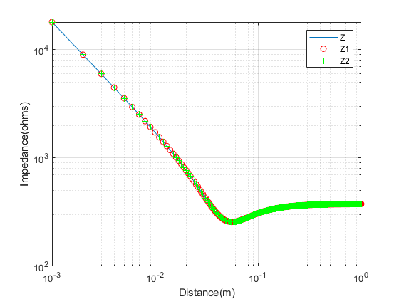
2. We have used three methods to plot the impedance; from definition of impedance (Z=E/H), from the formula for impedance (Z1) and simplified formula for impedance (Z2).
3. The exact formula for calculating the length of Near Field is given as NF=2*(D^2)/l, where l is the wavelength and D is the length of the antenna. But this formula is only valid for large antennas.
Reference:
https://nptel.ac.in/content/storage2/courses/108101092/Week-2-Dipole%20Antenna.pdf
5 thoughts on “Near Field of an Antenna”
A very good approach. But I have a question:
Can we estimate the DOAs of near field sources using a uniform linear array? If yes, then how? I mean if I want to estimate the direction and range of source1, the same for source2 and source3 separately, then how will I do it mathematically?
Can you give me a signal model of the received signal by the ULA of the three near field sources?
Regards,
For my Uniform Linear Array (ULA) calculations I assume that the receiver is in the far field. This results in Plane Wave assumption to be valid. Have not thought of Near Field scenario.
Thanks a lot for your prompt response. Sorry, I am not getting you. Do you mean that when you want to estimate the DOAs and ranges of near field sources using ULA, you assume them to be in far field?
If yes, then how is it possible because the near field sources waves are not plane waves as the literature says?
Like I said, I have not worked on DOA estimation in the Near Field. I think its possible to do it but more complicated.
Thanks a lot for your clarification.