
Array Factor and Element Factor
In the previous post we discussed the case of a Square Array which is a special case of a Rectangular Array. The code we shared can handle both the cases as well as Uniform Linear Array. We did briefly talk about the response of an element vs the response of an array, but we did not put forward the mathematical relationship. So here it is:
Response of an Array = Array Factor x Element Factor
In this post as well as previous posts we have assumed the element response to be isotropic (or at least omni-directional in the plane of the array) giving us an Element Factor of 1. So the array response is nothing but equal to the Array Factor. In this post we mostly discuss the 2D Array Factor but briefly touch upon the 3D case well at the end.
Excess Path Length Calculation
As discussed in the previous posts when a plane wave impinges upon an array its absolute phase is not that important (although it might be important in synchronization at the receiver but we defer that discussion for the moment). What is important is the relative phase at the array elements. This can be calculated by first determining the excess path length at each element from a reference element and then adding up the contribution of each element to the array pattern.
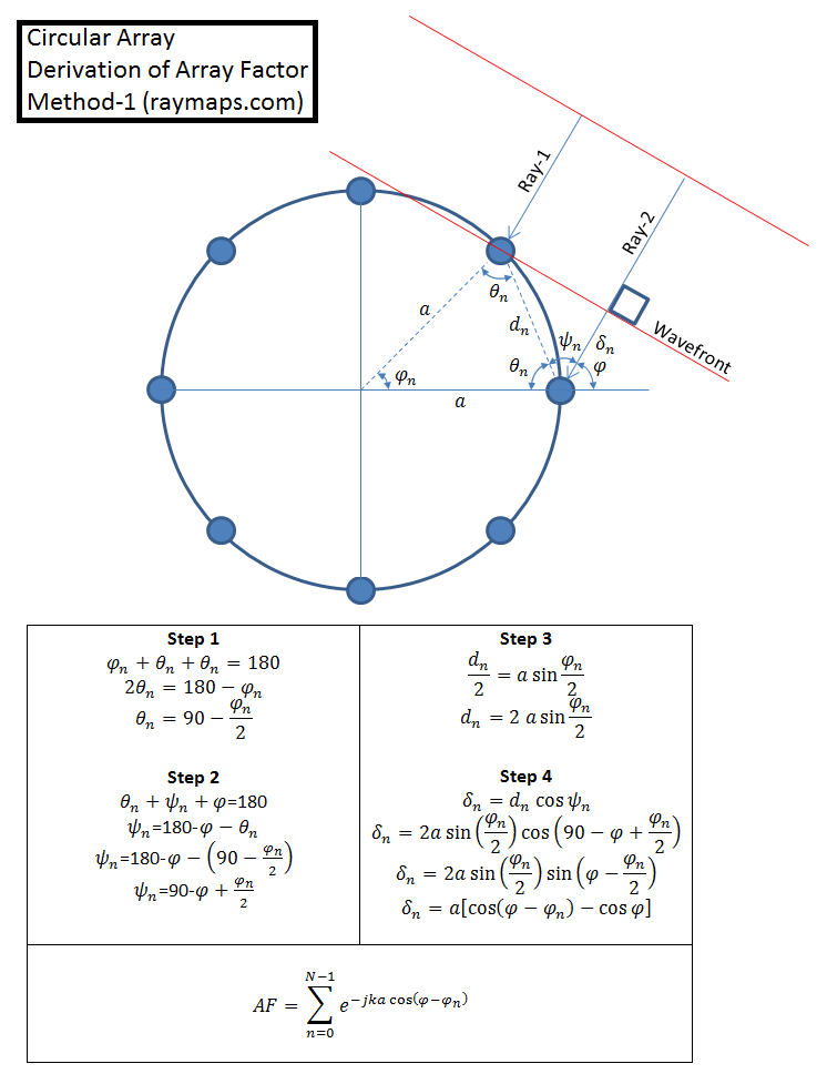
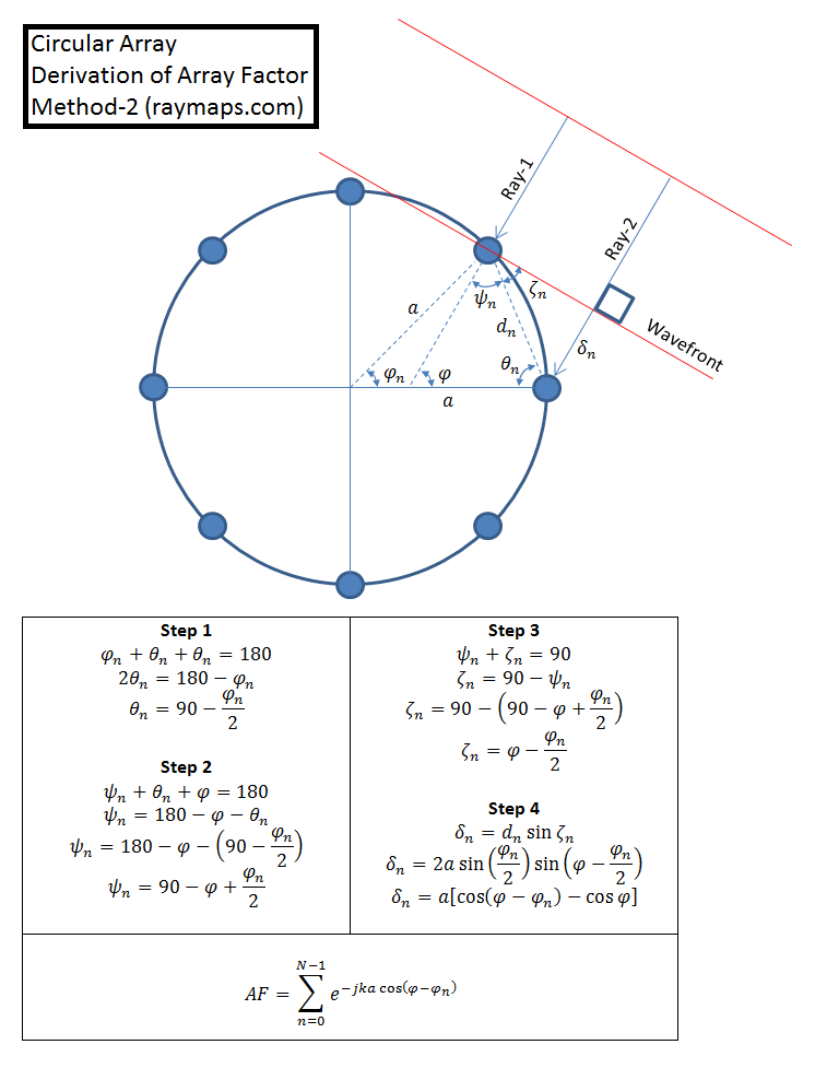
The excess path length calculation, for the elements of a Circular Array, is not as as straightforward as that for a Uniform Linear Array or a Rectangular Array. We show two methods for calculation of the excess path length, you can chose whichever you prefer. It’s no surprise that both methods give identical results. One point that needs to be clarified about the mathematical model below is that we drop the term cos(φ) from the final equation. This is because it is a common term for all the array elements and does not have any impact on the composite pattern (Array Factor).
Derivation of Array Factor
MATLAB Code for Calculating Array Factor of Circular Array
%%%%%%%%%%%%%%%%%%%%%%%%%%%%%%%%%
% CIRCULAR ARRAY WITH VARIABLE
% NUMBER OF ELEMENTS AND SPACING
% COPYRIGHT RAYMAPS 2018
%%%%%%%%%%%%%%%%%%%%%%%%%%%%%%%%%
clear all
close all

f=1e9;
c=3e8;
l=c/f;
k=(2*pi)/l;
N=8;
n=0:N-1;
phi_n=2*pi*n/N;
phi=0:pi/180:2*pi;
M=length(phi);
d_circular=l/2;
a=(N*d_circular)/(2*pi);
for m=1:M

  AF(m)=sum(exp(-i*k*a*(cos(phi(m)-phi_n))));

end
polar(phi, abs(AF))
8-Element Antenna Pattern
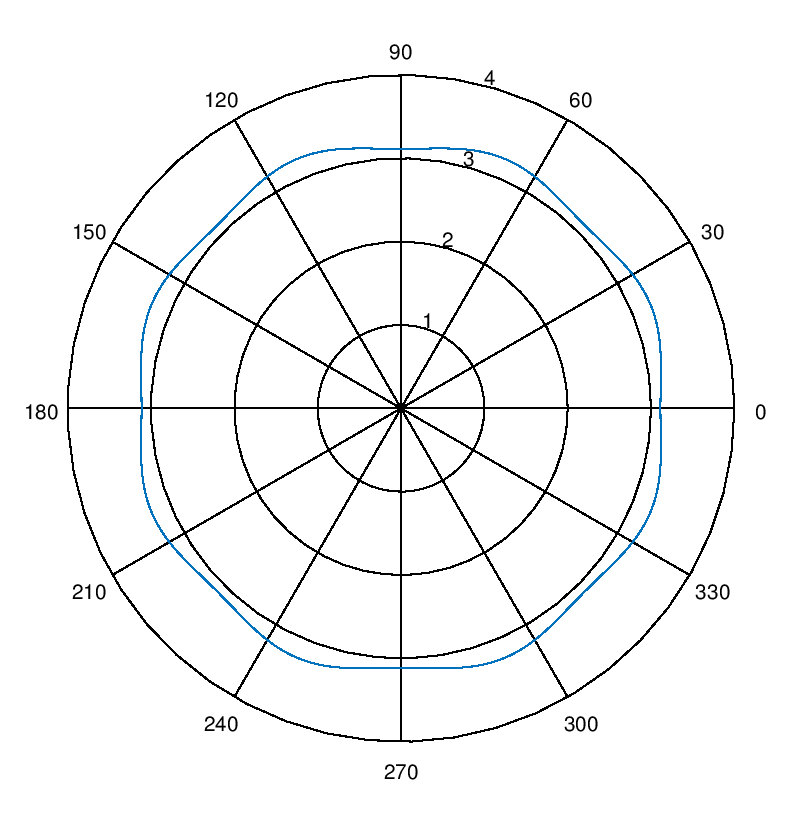
Discussion on 8-Element Antenna Pattern
It is seen that array pattern for 8-element array has almost a uniform response with a gain of about 3. Here the element separation, along the circumference of the ring, is set to half the wavelength. Different antenna patterns can be generated by varying the inter-element spacing (which determines the radius of the ring). More complicated patterns can be generated by using multi-ring antenna formations [1]. Also, it must be noted that we are simply adding the signal arriving at each of the elements without altering the phase or the amplitude. In actual implementations there is always a weighting pattern applied to the signals arriving at the array elements to get more useful patterns [2].
3D Array Factor
Lastly I would like to briefly comment on the 3D patterns that can be generated by using 3D Array Factors, a natural extension to the models discussed above. The equation of the 3D Array Factor is really not that complicated and has just one additional variable θ, which is nothing but the angle of elevation. In the above we have assumed that the angle of elevation to be 90 degrees. If the angle of elevation is not 90 degrees, that is we are not in the plane of the array, the array factor is modified to:
∑ e -jka(cosφ cosφnsinθ+sinφ sinφnsinθ)
∑ e -jkasinθ(cosφ cosφn+sinφ sinφn)
∑ e -jkasinθ(cos(φ -φn))
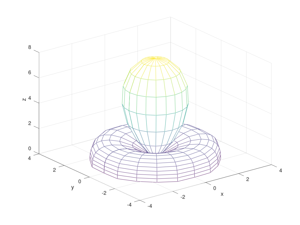
If we fix the value of φ to be zero and vary θ from -90 degrees to +90 degrees we get a very interesting pattern. This pattern shows that with isotropic array elements it is possible to have a maximum gain of 8 on the linear scale (or 9 dB on the logarithmic scale), which is expected from an array with 8 elements and Element Factor of unity. This can also be verified from the above equation by realizing that sin(θ)=sin(0)=0 and anything raised to the power of zero is one. Eight of these terms added together give a total gain of 8.
Note: Inter-element separation on the circumference is labelled as ‘d_circular’ and this is set to half the wavelength [2]. Based upon this the radius of the ring is calculated.
References
[1] F. Gozasht, G. R. Dadashzadeh, S. Nikmehr “A Comprehensive Performance Study of Circular and Hexagonal Array Geometries in the LMS Algorithm for Smart Antenna Applications”, Progress in Electromagnetics Research, PIER 68, 281-296, 2007
[2] Harry L. Van Trees “Optimum Array Processing”, Part IV of Detection, Estimation and Modulation Theory, Wiley 2002.
47 thoughts on “Fundamentals of a Circular Array – Mathematical Model and Code”
Dear author
How have you derived the 3D Array Factor? I thought a lot but I could not figure it out. Can you tell me the name of a book where I can find its detail? Also can you tell me the name of some books which give MATLAB codes for DOAs and beamforming?
Dear Yasir sab, is there any post on beamforming?
I have two sources in the far field whose angles are Theta1, Phi1 and Theta2, Phi2 respectively. The plane waves are incident on a circular array from which I want to estimate those angles and then I want to form two beams and send it at those angles. Can you guide me in this regard?
Yes there is a post.
Hallo Yasir, I’m not so good in calculation so my question is simple:
If I identify a specific frequency for a circular antenna array is there a way to choose the best number of antennas to match for that frequency and what must be the best distance beetween them.
Sorry if question is stupid but I hope you will contact me.
Thanks.
I don’t know what you mean by “best”. If you want to maximize the gain, more antennas the better. Usually antennas are placed half wavelength apart but its not necessary. You can experiment with different number of antennas and antenna spacing. That’s why I share the code and formulae 🙂
hi author
I am lucky to find your site. This will be a great help for me. I am trying to understand your derivation steps for the array factor of the circular array. The 1st two steps of Method1 are easy to understand but I don’t understand the 3rd step i.e., I don’t understand why have you written:
dn/2 = a sin (phin)/2
Can you help me in this regard please?
Hello,
That’s a good question. Please break down the triangle into 2 right angled triangles and you will understand. If not send me another message!
Cheers
Thank you dear author for you nice response. Yes, now it’s ok. I did it. Now another question is: Which antenna have you considered as a reference antenna? Is it the one on which Ray1 is incident? Or the one on which Ray2 is incident?
As far as I understand from the figure, the antenna on which Ray1 is incident is a reference antenna and then next downward is the nth antenna. am I right?
Any antenna can be taken as the reference antenna. It’s all relative.
Thank you for your nice response. That’s great.
Ok when we derive the Array Factor, what is its advantage because in the above graph after the MATLAB code, you have given about a circular ring. This means that the radiations from this circular array is in the form of a circle. Am I right? If yes, then I think it’s not so beneficial to us for transmission because the signal doesn’t move in a certain desired direction where the Receiver is placed. If we want to send this signal so produced from this circular array to that Receiver, how will we change the mathematical form?
I am just a learner in the very beginner stage, so please I beg your pardon if I ask some stupid question.
Yes it seems not so beneficial when observed in 2D. But plot it in 3D and you would see the advantage. Hope this helps!
Dear Yasir (John), is there any post on beamforming of planar arrays ?
Please explain the scenario you are working on in bit more detail.
Dear John I checked your response several times, but I don’t see any of your response to my recent post. Please respond so that I can proceed further. Regards,
I can give you general guidance but cannot debug the code for you.
Dear John normally I see that in a circular array, both the angles are there in the expression. I mean both the angle of elevation and the angle of azimuth are there in the expression but here you have given only one angle. If I want to bring the 2nd angle also in the expression, how will the model look like? Regards,
You are absolutely right, we need both the angles if we want to plot in 3D. We have plotted in 3D as you can see. Use the equations given at the end. Quite straightforward to modify the code using these equations.
Thanks a lot dear John for your prompt response. I found the following code on this page as below:
f=1e9;
c=3e8;
l=c/f;
k=(2*pi)/l;
N=8;
n=0:N-1;
phi_n=2*pi*n/N;
phi=-pi:pi/18:pi;
theta=0:pi/18:pi/2;
M=length(theta);
P=length(phi);
d_circular=l/2;
a=(N*d_circular)/(2*pi);
for p=1:P
for m=1:M
AF(m,p)=sum(exp(-i*k*a*sin(theta(m))*(cos(phi(p)-phi_n))));
x(m,p)=abs(AF(m,p))*sin(theta(m))*cos(phi(p));
y(m,p)=abs(AF(m,p))*sin(theta(m))*sin(phi(p));
z(m,p)=abs(AF(m,p))*cos(theta(m));
end
end
mesh(x,y,z)
%—————————————-
If I take two sources at angles 30, 50 and -30 -50 respectively in a desired vector like this: desired_angles=[30 50 -30 -50];
Now what changes will I do in the above code to estimate these angles with MUSIC algorithm? Regards,
Please see my post on MUSIC and ESPRIT. Frequency estimation and angle of arrival estimation is the same thing.
Dear John 1st of all thanks a lot to you for your precious time that you give for replying to our post.
I tried to convert the above code for estimating my desired angles using MUSIC algorithm according to your instructions. My code is as below:
clear;clc
f=1e9;
c=3e8;
l=c/f;
k=(2*pi)/l;
N=8;
%n=0:N-1;
n=transpose(1:N);
phi_n=2*pi*n/N;
phi=-pi:pi/18:pi;
theta=[pi/6, pi/3, pi/2];%0:pi/18:pi/2;
%M=length(theta);
%P=length(phi);
d_circular=l/2;
a=(N*d_circular)/(2*pi);
% for p=1:P
% for m=1:M
% AF(m,p)=sum(exp(-1i*k*a*sin(theta(m))*(cos(phi(p)-phi_n))));
% x(m,p)=abs(AF(m,p))*sin(theta(m))*cos(phi(p));
% y(m,p)=abs(AF(m,p))*sin(theta(m))*sin(phi(p));
% z(m,p)=abs(AF(m,p))*cos(theta(m));
% end
% end
% mesh(x,y,z)
%x1=exp(-1i*(n-1)*2*pi*d*cos(theta(1))/l);
x=exp(-1j*k*a*sin(theta(1))*(cos(phi(p)-phi_n)))*sin(theta(1))*cos(phi(p));
y=exp(-1j*k*a*sin(theta(2))*(cos(phi(p)-phi_n)))*sin(theta(2))*sin(phi(p));
z=exp(-1j*k*a*sin(theta(1))*(cos(phi(p)-phi_n)))*cos(theta(3));
ReceivedSignal=x+y+z;
ReceivedSignal=ReceivedSignal(:);
%%%%% MUSIC/Pisarenko Spectrum Generation %%%%%
M=100;
p=2;
f=0:fs/(N-1):fs;
w=2*pi*f/fs;
cov_matrix=zeros(M,M);
for n=1:N-M+1
cov_matrix=cov_matrix+(x(n:n+M-1))*(x(n:n+M-1))’;
end
[V,lambda]=eig(cov_matrix);
e=exp(j*((0:M-1)’)*w);
den=zeros(length(w),1);
for n=1:M-p
v=(V(:,n));
den=den+(abs((e’)*v)).^2;
end
PSD_MUSIC=1./den;
plot(f,10*log10(PSD_MUSIC/max(PSD_MUSIC)),’linewidth’,3,’ro-‘)
hold on
%———————–End————————-
But this code doesn’t run and gives errors. I tried several times to remove the errors but in vain. Can you guide me further, where am I making mistakes?
Regards,
Dear John hope you are doing well. The code you have given above is reproduced here:
f=1e9;
c=3e8;
l=c/f;
k=(2*pi)/l;
N=8;
n=0:N-1;
phi_n=2*pi*n/N;
phi=-pi:pi/18:pi;
theta=0:pi/18:pi/2;
M=length(theta);
P=length(phi);
d_circular=l/2;
a=(N*d_circular)/(2*pi);
for p=1:P
for m=1:M
AF(m,p)=sum(exp(-i*k*a*sin(theta(m))*(cos(phi(p)-phi_n))));
x(m,p)=abs(AF(m,p))*sin(theta(m))*cos(phi(p));
y(m,p)=abs(AF(m,p))*sin(theta(m))*sin(phi(p));
z(m,p)=abs(AF(m,p))*cos(theta(m));
end
end
mesh(x,y,z)
% ————————————————————————
Note: It gives us the 3D Array response as you have shown above.
Question1: What do you mean by 3D Array? you mean that the sensors are placed in the form of a sphere instead of a circle?
Question2: This code gives us the response pattern. But if I write the desired angles in the form of a vector like:
desiredAngles=[20 30 40 50 60 70 80 110] ;
as is usually written for DOA estimation in MUSIC algorithm. Then what changes should we do in this code? Further if it’s a 3D array, then it must estimate both the elevation angles as well as the azimuth angles. I tried like this but its not giving me estimated DOAs:
f=1e9;
c=3e8;
l=c/f;
k=(2*pi)/l;
N=8;
n=0:N-1;
phi_n=[20 30];%phi_n=2*pi*n/N; % [Elevation1 Elevation2];
phi=[40 50];%phi=-pi:pi/18:pi; %[Azimuth1 Azimuth2];
theta=0:pi/18:pi/2;
M=length(theta);
P=length(phi);
d_circular=l/2;
a=(N*d_circular)/(2*pi);
for p=1:P
for m=1:M
AF(m,p)=sum(exp(-i*k*a*sin(theta(m))*(cos(phi(p)-phi_n))));
x(m,p)=abs(AF(m,p))*sin(theta(m))*cos(phi(p));
y(m,p)=abs(AF(m,p))*sin(theta(m))*sin(phi(p));
z(m,p)=abs(AF(m,p))*cos(theta(m));
end
end
mesh(x,y,z)
Dear John I had asked you a question that how can we use this code for concentric circles, so your reply was as:
“You can create as many circles as you want with the required radius and number of elements, and then add the responses.”
So I have tried like this:
clear all; clc
f=1e9;
c=3e8;
l=c/f;
k=(2*pi)/l;
N1=8; % For 1st circle
N2=10;% For 2nd circle
N3=12;% For 3rd circle
N4=14;% For 4th circle
n1=0:N1-1;
n2=0:N2-1;
n3=0:N3-1;
n4=0:N4-1;
phi_n1=2*pi*n1/N1;
phi_n2=2*pi*n2/N2;
phi_n3=2*pi*n3/N3;
phi_n4=2*pi*n4/N4;
phi=0;
theta=-pi:pi/180:pi;
M=length(theta);
d_circular=l/2;
a1=(N1*d_circular)/(2*pi);% 1st radius
a2=(N2*d_circular)/(2*pi);% 2nd radius
a3=(N3*d_circular)/(2*pi);% 3rd radius
a4=(N4*d_circular)/(2*pi);% 4th radius
for m=1:M
AF1(m)=sum(exp(-i*k*a1*sin(theta(m))*(cos(phi-phi_n1))));% Response of 1st circle
AF2(m)=sum(exp(-i*k*a2*sin(theta(m))*(cos(phi-phi_n2))));% Response of 2nd circle
AF3(m)=sum(exp(-i*k*a3*sin(theta(m))*(cos(phi-phi_n3))));% Response of 3rd circle
AF4(m)=sum(exp(-i*k*a4*sin(theta(m))*(cos(phi-phi_n4))));% Response of 4th circle
end
AF=AF1 + AF2+ AF3 + AF4; % Combined response due to all circles
polar(theta, abs(AF))
title(‘Combined response’)
figure
polar(theta, abs(AF1))
title(‘1st circle response’)
figure
polar(theta, abs(AF2))
title(‘2nd circle response’)
figure
polar(theta, abs(AF3))
title(‘3rd circle response’)
figure
polar(theta, abs(AF4))
title(‘4th circle response’)
%%%%%%%%%%%%%%%%%%%%%%%
Now my question is what improvement/improvements has the combined effect brought in the individual response?
My 2nd question is I want to see these graph on a single graph instead of separate windows. I tried like this:
polar(theta, abs(AF1), theta, abs(AF2), theta, abs(AF3), theta, abs(AF4), theta, abs(AF) )
But it gives me the error as:
Error using polar
Too many input arguments.
Error in concentricCircles (line 62)
polar(theta, abs(AF1), theta, abs(AF2), theta, abs(AF3), theta, abs(AF4), theta, abs(AF))
Please apply the concept of superposition.
Mr John How to plot 2 polar plots on same graph with centres separated by distance in matlab
Can you not shift the origin by the distance, like in a 2D circle.
Hi dear John!
Indeed I didn’t saw another site like this till now. You have done a wonderful job by giving us this site. Its very helping site. I have certain confusion in the above code. In this what is meant by the statement: d_circular=l/2;
Is it the circumference of the circle?
Further, what is: a=(N*d_circular)/(2*pi);
Is it the radius of the circe? If yes, then from mathematics, we know that the circumference of a circle is given by circumeference=2*pi*r which implies r=circumfernce/2*pi. But here it is N*d_circular? So does “d_circular” denote circumference? or this whole thing i.e., N*d_circular represents the circumference?
Regards,
N*d_circular is the circumference which is also equal to 2*pi*a, where ‘a’ is the radius. Hope this clarifies.
Thank you very much dear John for your response. Further if I want to use this code for arrays of concentric circles, then what changes should I do in this code.?
You can create as many circles as you want with the required radius and number of elements, and then add the responses. Hope this helps!
Sorry for my interruption. I think d_circular is the arc length between two elements. Then the equation satisfies.
Dear John I have heard from one of my friend that the response of 2L shaped array is better than 1L shaped array? When I asked him how? He replied that we can estimate DOAs accurately with 2L shaped array than with 1L shaped array? But how? Then he didn’t explain further. So, I ask the same question from you that how?
That’s the standard way, how AF is written in terms of delta…same relationship exists in all the posts…correct me if I am wrong?
Thank you dear John for your reply. I am not saying you are wrong. I learn a lot from you, so I became your student, then how can I say that you are wrong. I mean to say that you have written the expression for AF in case of circular array directly. But in case of ULA, you have taken your start from the 1st step i.e., r=e^-iwt. see the URL: http://www.raymaps.com/index.php/fundamentals-of-a-uniform-linear-array-ula/mathematical-framework-for-ula-four-elements/
Now if I take the same r=e^-iwt=e^-i2pift=e^-i2pi(ct/lambda)=e^-i2pi(x/lambda).Then I cannot figure out where should I put the value of this delta in this expression? That’s why I am asking. The rest you can guide me better. Thanks once again.
Angular Wave Number=k=2*pi/lambda…AF is sometimes written in terms of k rather than wavelength or frequency. x=c*t is the distance travelled. Instead of x you can just write delta, since you interested in access distance only, not the absolute value.
Thank you very much dear John. Yes, now its ok. Actually I could not figure it out. But now its ok. Thanks once again.
The results of Uniform Linear Array(ULA) are better than Uniform Circular Array (UCA). Then why should we use circular array instead of ULA?
How do you define better? what are the metrics that you are considering?
Thank you very much dear John for your response. I look at the two graphs, you have given. For ULA, the graph is given on URL: http://www.raymaps.com/index.php/fundamentals-of-a-uniform-linear-array-ula/
And the circular is given on this page. If we look at the two graphs, the graph of ULA is directional but here in case of UCA, there is no directionality. Its just in ring shape. It means that if we want to estimate the DOA , then ULA should give better results.
I guess you are right but please also look at the 3D graph.
Thank you very much dear John for your response. Yes, if we look at the 3D graph, again there is some wastage of energy in the ring form which is not there in case of ULA. So, again in my opinion ULA seems to be better than the UCA. But I am not an expert like you, you can comment better whether I am right or wrong.
2ndly I have a complaint. Sometimes, you give reply to my question and sometimes you don’t give reply to my question. Why it is so? I am a learner and I want to become an expert like you, so I request you, please give reply to my each question so that my confusion is rectified. By the way, again I am going to ask you a question:
In the above mathematical model of UCA , you have derived delta value, but then you have directly written AF=sigma…..
Though this proof made me understand how to find value of delta, but does not tell me how you got the expression of AF?
Regards,
That’s the standard way, how AF is written in terms of delta…same relationship exists in all the posts…correct me if I am wrong?
I liked your post very much as this helped me a lot. I implemented the MATLAB code by including the 3D array factor and kept phi as constant. The code is given below:
ERRONEOUS CODE REMOVED. PLEASE SEE CORRECT IMPLEMENTATION BELOW.
(1)But the graph is not the same as yours.
(2) If I want to keep both the parameters variable and want to see graph of 3D, then how can we change this code?
clear all
close all
f=1e9;
c=3e8;
l=c/f;
k=(2*pi)/l;
N=8;
n=0:N-1;
phi_n=2*pi*n/N;
phi=0;
theta=-pi:pi/180:pi;
M=length(theta);
d_circular=l/2;
a=(N*d_circular)/(2*pi);
for m=1:M
AF(m)=sum(exp(-i*k*a*sin(theta(m))*(cos(phi-phi_n))));
end
polar(theta, abs(AF))
Thank you very much for your kind response. it works now.
theta=-pi:pi/180:pi; what is the meaning of this statement.
This statement means that theta has values from -pi to pi with increments of pi/180. Or in degree terms, theta goes from -180 degrees to 180 degrees with 1 degree increments.
f=1e9;
c=3e8;
l=c/f;
k=(2*pi)/l;
N=8;
n=0:N-1;
phi_n=2*pi*n/N;
phi=-pi:pi/18:pi;
theta=0:pi/18:pi/2;
M=length(theta);
P=length(phi);
d_circular=l/2;
a=(N*d_circular)/(2*pi);
for p=1:P
for m=1:M
AF(m,p)=sum(exp(-i*k*a*sin(theta(m))*(cos(phi(p)-phi_n))));
x(m,p)=abs(AF(m,p))*sin(theta(m))*cos(phi(p));
y(m,p)=abs(AF(m,p))*sin(theta(m))*sin(phi(p));
z(m,p)=abs(AF(m,p))*cos(theta(m));
end
end
mesh(x,y,z)
Thank you very much for your kind response. But can we make this code as a function inside which we give our desired vector consisting of our theta and phi’s as:
myDesired=[theta1 theta2 theta3 theta4 phi1 phi2 phi3 phi4]=[ 35 55 67 85 45 70 170 250 335]
then I call that function from GA(genetic algorithm) and after completing the iterations, it gives me the estimated vector nearly equal to myDesired. If yes, how can we do that ?