
Introduction
A Uniform Linear Array (ULA) is a collection of sensor elements equally spaced along a straight line. The most common type of sensor is a dipole antenna that can transmit and receive Electromagnetic Waves over the air. Other types of sensors include acoustic sensors that may be used in air or under water. The requirements of a ULA are different for different applications but the most common requirement is to improve the Signal to Noise Ratio (SNR) and to improve its response (Gain) in a particular direction. The second property means that the array accepts a signal from a particular direction and rejects the signal from another direction just as required in Radar.
Excess Path Length
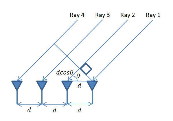
The graphical representation and the mathematical framework for the problem are shown below. It is assumed that Electromagnetic Waves (Rays) arrive at the array in the form of a plane wave. This means that there is a large distance between the transmitter and receiver (the receiver is in the far field of the transmitter). The array elements are separated by a distance ‘d’ which must be less than or equal to half the wavelength (similar to the concept of minimum sampling frequency in DSP). Now we can see that the second ray travels an excess distance dcos(θ). Similarly, the third and fourth rays travel an excess distance of 2dcos(θ) and 3dcos(θ) respectively. In array processing it is this excess distance between the arriving rays that is important, absolute distance from the source does not matter (unless you are interested in large scale effects such as path loss). This excess distance between the different rays determines if the signals are going to add constructively or destructively.
Mathematical Model of a ULA
Simulation Methodology
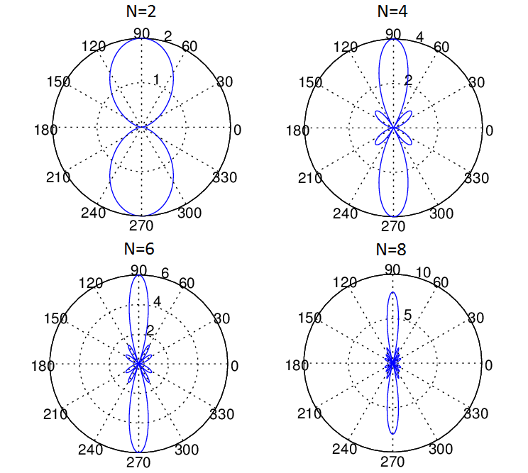
Given below is the MATLAB code for the scenario shown in the figure above. We have considered two methods, one employing a ‘for-loop’ and another using matrix manipulation. The second method is usually preferred as it is much faster and also allows us to directly apply techniques from linear estimation theory. We have plotted the array pattern for four cases with N=2,4,6 and 8. It is seen that as the number of array elements increases the Gain (or Directivity) of the array increases. In the case shown below we have considered that the four received signals are added with equal weights (w=1), but these weights can be adjusted to get various beam patterns (weights are typically complex quantities adjusting both phase and amplitude of the signal). This is typically called Beamforming and we will discuss this in a future post.
Matlab Code
FOR LOOP IMPLEMENTATION
%%%%%%%%%%%%%%%%%%%%%%%%%%%%%%%%%%%%
% SIMPLE UNIFORM LINEAR ARRRAY
% WITH VARIABLE NUMBER OF ELEMENTS
% COPYRIGHT RAYMAPS (C) 2018
%%%%%%%%%%%%%%%%%%%%%%%%%%%%%%%%%%%%
clear all
close all
f=1e9;
c=3e8;
l=c/f;
d=l/2;
no_elements=4;
theta=0:pi/180:2*pi;
r=zeros(1,length(theta));
for n=1:no_elements
   dx(n,:)=(n-1)*d*cos(theta);
   r=r+exp(-i*2*pi*(dx(n,:)/l));
end
polar(theta,abs(r),'b')
title ('Gain of a Uniform Linear Array')
MATRIX IMPLEMENTATION
%%%%%%%%%%%%%%%%%%%%%%%%%%%%%%%%%%%%
% SIMPLE UNIFORM LINEAR ARRRAY
% WITH VARIABLE NUMBER OF ELEMENTS
% MATRIX IMPLEMENTATION
% COPYRIGHT RAYMAPS (C) 2018
%%%%%%%%%%%%%%%%%%%%%%%%%%%%%%%%%%%%
clear all
close all
f=1e9;
c=3e8;
l=c/f;
d=l/2;
no_elements=4;
theta=0:pi/180:2*pi;
n=1:no_elements;
n=transpose(n);
A=(n-1)*(i*2*pi*d*cos(theta)/l);
X=exp(-A);
w=ones(1,no_elements);
r=w*X;
polar(theta,abs(r),'r')
title ('Gain of a Uniform Linear Array')
MATLAB Plot
Note: For a Uniform Linear Array with N elements and half wavelength inter-element spacing the Half Power Beam Width (HPBW) can be estimated as 1.78/N Radians [source]. For the four element case shown above the formula gave a HPBW of 25.49 degrees whereas our simulation yielded 26.20 degrees. For ten element case the formula gave a HPBW of 10.19 degrees whereas the simulation result was 10.20 degrees. Similarly the result for 20 elements is also quite accurate. So we can say that the formula does help us to get a ballpark estimate and gives progressively more accurate results as the number of elements is increased. For a general case where the inter-element spacing is not equal to half wavelength the formula is 0.89*(wavelength/total aperture length).
Lastly, for those who still do not know what Half Power Beam Width also known as 3dB Bandwidth means, it is the width of the main lobe in degrees 3dB down from the peak value of the radiation pattern.
29 thoughts on “Fundamentals of a Uniform Linear Array (ULA)”
Hello,
I have a passive ULA (without amplitude weighing) which when steered at 45° shows an equally strong lobe at -45° and these two equally strong lobes are mirrored too so now i have 4 strong lobes when i just want the ULA to steer at 45°. What could be wrong possibly? I am not visualising the lobes (beams) in polar plot, rather i calculate the rate and plot the heatmap
It’s like FFT, you get two lobes, one original and one mirrored. I do not understand why you are getting four!
can u give me all information about mathematical model of ULA ??
Dear John !
I have learned that with the help of ULA, we can estimate elevation angle only. I have a confusion in this. Suppose my ULA is along x-axis, then definitely we can estimate elevation angle with this. But if my ULA is placed along y-axis, then how can we estimate elevation angle. I think in that case, we can estimate azimuth angle. Am I right? Please guide me in this regard.
Regards,
I found this helpful “In recent years, much research has been done on the topic of localization by estimating the directions-of-arrival (DOA) (i.e., azimuth angles and elevation angles) and ranges of multiple targets in many applications, such as radar, sonar, and wireless communications. Many methods based on one-dimensional (1D) uniform linear array (ULA) have been proposed for estimating azimuth angle, or joint range and azimuth angle estimation, such as the well-known multiple signal classification (MUSIC) algorithm and estimation of signal parameters via rotational invariance techniques (ESPRIT) algorithm, and the generalized MUSIC and ESPRIT. Two-dimensional (2D) DOA estimation for azimuth and elevation angle has been further extended from the conventional 1D estimation methods based on some 2D arrays.” https://www.mdpi.com/1424-8220/18/5/1634/htm
I have a confusion regarding this. Suppose my ULA is along x-axis only, then definitely we can estimate elevation angle with this. But if my ULA is placed along y-axis only, then how can we estimate elevation angle. I think in that case, we can estimate azimuth angle instead of elevation angle. Am I right? Please guide me in this regard.
I think you need 2D array to estimate both the azimuth and elevation.
Thank you very much dear John for your response!
Dear John I know that we need 2D array for estimating both the angles. But I want to estimate only single angle with 1D array. So my question is:
1-with ULA only along x-axis, we can estimate elevation angle only
2- Now if we lift this array from x-axis and place it along y-axis, and no other array, then which angle can we estimate with this ULA: elevation or azimuth?
Regards,
x and y is aribtrary. In general for a ULA you cannot estimate the angle in the plane perpendicular to ULA axis.
Thank you very much dear John for your response. Your reply was: ” x and y are arbitrary. In general for a ULA you cannot estimate the angle in the plane perpendicular to ULA axis.”
What do you mean by this statement? If we place antennas along x-axis, then definitely the axis of that array will be x-axis. Now which plane is perpendicular to this axis? In my opinion, these are xy-plane, xz-plane and yz-planes. So according to your reply, we cannot estimate the angle in these planes? Isn’t that? If it is so, then why do we find in “Literature” that if ULA is along x-axis, we find the elevation angle only. Now you know that elevation angle is the angle of the line joining the target and the axis of the array (in this case x-axis). Based on this logic, this elevation angle is in the xy-plane which is perpendicular to the axis of the array. But you say, we cannot estimate this angle? So I got confused with your this reply. Can you guide me further? Regards,
yz plane is perpendicular to x-axis.
Thanks for your response dear John.
Gooday all, the contributions are excellent , am a beginner but trying to input the codes in matlab 2007b , its showing undefined function, what can i do ,i really want to be in phase with the contributions , thanks
Thanks Amadi. Can you share the exact error you are getting. I have tried the code again and I am not seeing any error. Also, would recommend you use latest version of Octave, its free!!!
Dear John your blog is very much useful for array signal processing.
Suppose we have a coprime array in which we take two subarrays i.e., M and N arrays where M and N are coprime numbers. In this the two sub-arrays are placed along a straight line such that the 1st element is reference. Then we take elements from M and N sub-arrays and make a single array. The distance of M elements from reference is Nd, 2Nd, 3Nd ,… and distance of N elements from reference is Md, 2Md, 3Md,….
Now the formulas for the last two rows of a steering matrix are given by:
x2ndlast=exp(-jpi(N-1)Mcos(u1))+exp(-jpi(N-1)Mcos(u2))+……+exp(-jpi(N-1)Mcos(last element of u))
xLast=exp(-jpi(M-1)Ncos(u1))+exp(-jpi(M-1)Ncos(u2))+……+exp(-jpi(M-1)Ncos(last element of u))
My question is: if I take a vector u in which I take my desired amplitudes and thetas e.g.
u=[A1 A2 A3 A4 theta1 theta2 theta3 theta4]
u=[1 3 5 7 50 130 150 170]
and put these values in the above formulas, how can I get a row vector x(x, M+N-1) that contains the values of all array?
Q. I have a problem regarding my code when I try to plot it in Polar I receive wrong plotting.
A. Please find the corrected code below.
clc clear clear all close all hidden f=input('Please enter operating frequency in Hz :\n–>'); N=input('Please enter no of elements(N) :\n–>'); disp('Press any key to see the value of wavelength lambda in meters:') pause disp('==============================================================') lambda=(3e8)/f %lambda=c/f %The value is in meters disp('=========================================') disp(' ') pause d=input('Please enter distance d in meters between elements :\n–>'); K=2*pi/lambda; theta=0:0.01:180; U=(0.5*K*d)*cos(theta*pi/180); R0db=input('Please enter side lobe ratio in db :\n–>'); c=chebwin(N,R0db); b=c'; x=mod(N,2); if x==0; for i=1:(N/2); a(i)=b((N/2)+i); end elseif x~=0; for i=0:floor(N/2); a(1+i)=b(round(N/2)+i); end end if x==0; AF=0; for n=1:N/2; AF=AF+a(n).*cos(((2*n-1))*U); end elseif x~=0; AF=0; for n=1:round(N/2); AF=AF+a(n).*cos((2*(n-1))*U); end end figure plot(theta,abs(AF)) title('Pattern of array in linear scale'); AFdb=20*log10(abs(AF)); figure plot(theta,AFdb) title('Pattern of array in db scale'); figure polar(theta*pi/180,abs(AF)); title('Polarization Factor Vs theta');how can i convert this code from uniform to non uniform linear array
If the non-uniform spacing is also a multiple of ‘d’ you can just change ‘n’ from being 1,2,3,4 to lets say 1,2,4,8 etc.
Today I was searching for the mathematical model of Circular Array. I found your stuff and it helped me a lot. I am also looking for the mathematical model of co-prime array with Matlab code. Can you help me in this regard? Waiting for your prompt response.
Regards,
i’d like to design linear array antenna according to tschepy chev with two sets of coefficients z&y what
Hi,
Great Article. Thank you so much for this. Please I wanted to ask how you were able to get the Half Power Beam width from your simulation (Code). I am trying to do that but I cannot seem to get it.
Thank you.
Hi,
Happy that you liked my post!
One way to calculate HPBW is to vary theta and calculate the array response for each value of theta. Measure how many degrees you need to increase to get from peak array response to 3dB down and double it. That will give you Half Power Beam Width.
PS: You might need to take 20*log10(r) and not 10*log10(r).
Hope this helps.
YA
OK I will give it away. Use the following piece of code after running the above code:
r_dB=20*log10(abs(r)/max(abs(r))); for m=2:length(theta) if (r_dB(m-1))>(-3)&&(r_dB(m))<(-3) HPBW_degrees=2*(theta(m)-pi/2)*180/pi end endthank you
http://www.ju.edu.jo