Some Background
We have previously discussed beamforming for single carrier signals. Now we turn our attention to multicarrier signals particularly at mmWave where the bandwidths are two orders of magnitude (100x) higher than at sub 6GHz band. We want to investigate that whether there is any distortion in the array response due to high signal bandwidths at mmWave.
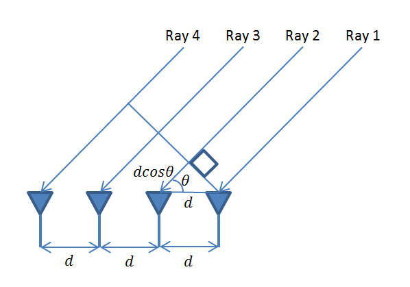
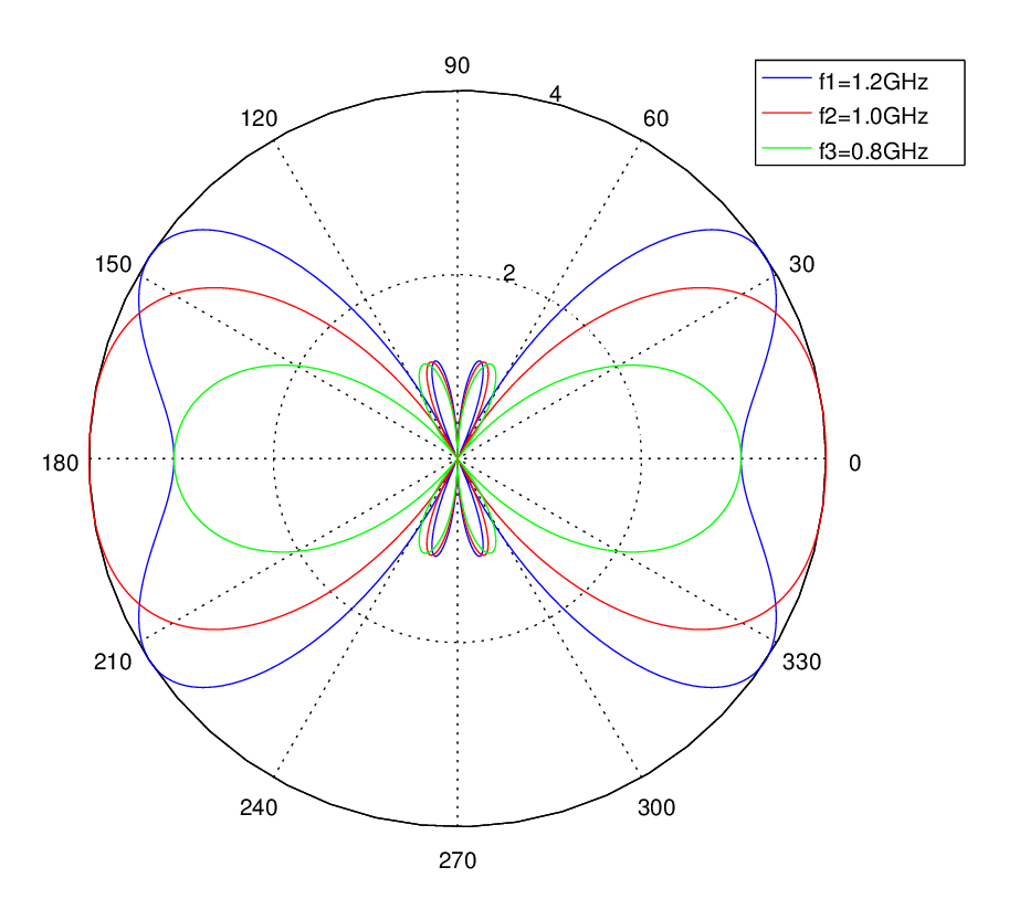
But let us start with the case that we have discussed so far i.e. 1GHz single carrier case and a Uniform Linear Array (ULA). We then add two other carriers at 1.2GHz and 0.80GHz, quite an extreme case, stretching the bandwidth to 400MHz. Antenna spacing is still λ/2=0.15m corresponding to the center frequency of 1GHz.
Broadband Signal and Spatial Sampling
So basically we are breaking the spatial sampling theorem (d < λ/2) at 1.2GHz where the element spacing should be less than 0.1250m. We are still OK at 800MHz where the element spacing must be less than 0.1875m. But we must clarify that the sampling theorem is given for the worst case, when the signal is arriving from the Endfire of a ULA [need a reference]. For a plane wave arriving from the Broadside, all rays would add up coherently irrespective of inter-element spacing.
Simulation Scenario
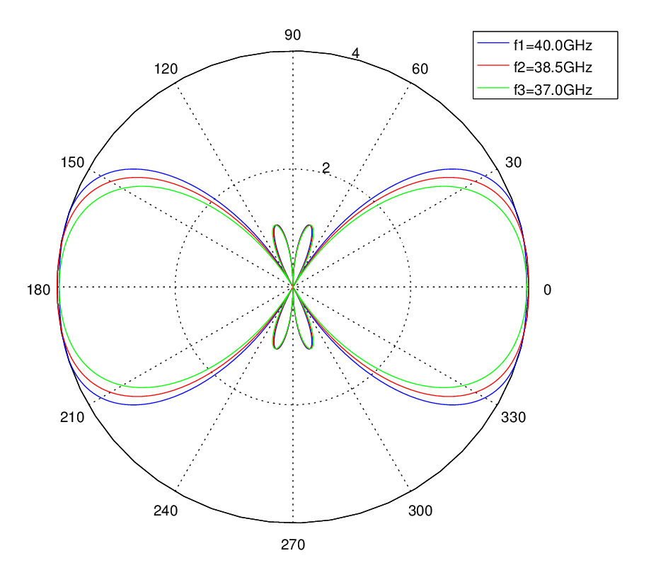
Below we give the simulation results and MATLAB code used to generate these results. First we consider the standard 1GHz case (with 400MHz bandwidth) and then we venture on to the more interesting case of a mmWave signal with three carriers at 37.0GHz, 38.5GHz and 40.0GHz (total bandwidth of 3.0GHz). These are not some random numbers, there is actually a mmWave frequency allocation at 37GHz – 40GHz.
Simulation Results
It is seen that the departure of array response from the ideal depends upon both the bandwidth of the signal (Δf = fmax-fmin) as well as the center frequency (fc). In fact it depends on the ratio Δf/fc and the smaller this ratio the better. As discussed above, at the lower frequency of 1GHz this ratio is 0.40 (Δf/fc=0.4/1.0) whereas at mmWave this ratio is only 0.08 (Δf/fc =3.0/38.5). While there is some deviation in array response in the first case there is hardly any in the second.
MATLAB Code
%%%%%%%%%%%%%%%%%%%%%%%%%%%%%%%%%%%%
% SIMPLE UNIFORM LINEAR ARRAY
% WITH VARIABLE NUMBER OF ELEMENTS
% MATRIX IMPLEMENTATION
% COPYRIGHT RAYMAPS (C) 2018
%%%%%%%%%%%%%%%%%%%%%%%%%%%%%%%%%%%%

clear all
close all

f1=1.2e9;
f2=1.0e9;
f3=0.8e9;
c=3e8;
l1=c/f1;
l2=c/f2;
l3=c/f3;
d=l2/2;
no_elements=2;
n=1:no_elements;
n=transpose(n);
w=exp((n-1)*(i*2*pi*d*cos(pi/2)/l2));
w=transpose(w);
theta=0:pi/180:2*pi;

A=(n-1)*(i*2*pi*d*cos(theta)/l1);
X=exp(-A);
r=w*X;
polar(theta,abs(r),'b-')
hold on

A=(n-1)*(i*2*pi*d*cos(theta)/l2);
X=exp(-A);
r=w*X;
polar(theta,abs(r),'r-')
hold on

A=(n-1)*(i*2*pi*d*cos(theta)/l3);
X=exp(-A);
r=w*X;
polar(theta,abs(r),'g-')
hold off

title ('Gain of a Uniform Linear Array')
legend('f1=1.2GHz','f2=1.0GHz','f3=0.8GHz')
Note:
- We can observe the appearance of grating lobes at 1.2GHz. These lobes have the same magnitude as those at 1.0GHz however they make the array response to be much wider along Endfire.
- We can easily rotate the main beam towards Broadside by modifying the angle
(phi) of the Steering Vector from 0 to pi/2 as given in the following piece of code: w=exp((n-1)*(i*2*pi*d*cos(phi)/l2)). - Here we have assumed that the response of the array to a wideband signal is equal to sum of the responses of the individual narrowband signals, so we can analyze their responses independently. But in reality there are non-linear effects such as intermodulation effects and we need to calculate the response of the composite signal.
Bottom Line
Due to the high carrier frequencies at mmWave the high bandwidth of signals has minimal impact, so traditional beamforming techniques would still work. However, one must be careful not to overlook non-linear effects and this would be the subject of a future post.