
Some Background on MSK
I – In the previous post we presented the mathematical model and code for BER calculation of a popular modulation scheme called MSK. However in the code we shared, we only considered one sample per symbol, which makes MSK look like BPSK. While BPSK symbols fall on the real axis, MSK symbols alternate between real and imaginary axes, progressing by π/2 phase during each symbol period. MSK signal thus has memory and this can help in demodulation using advanced techniques such as Viterbi Algorithm.
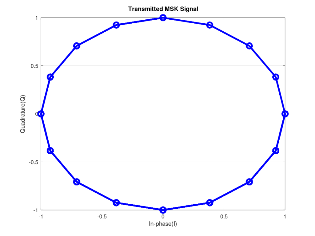
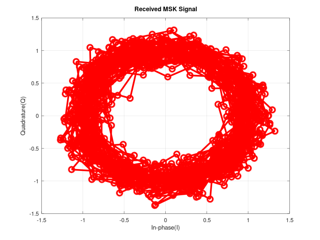
II – But the real beauty of MSK is only visible when we consider multiple samples per symbol. The figures below show the transmitted and received MSK signal in an AWGN channel. We considered four samples per symbol but this is not mandatory and with the code given below it is possible to select any number of samples per symbol without altering the BER results. Another interesting point to note from the figures given below is that the trajectory of MSK signal does not pass through the origin making it suitable for amplification by non-linear amplifiers[1].
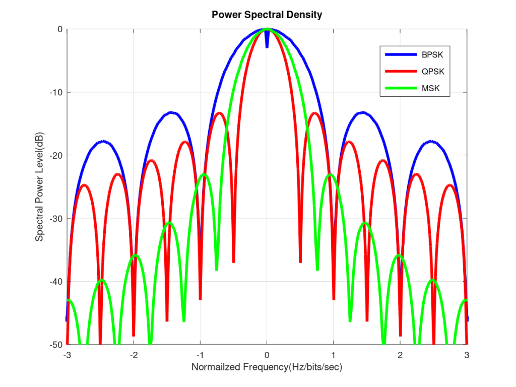
III – As discussed previously the advantage of having a continuous phase is that the PSD (Power Spectral Density) has very low sidelobes which helps in reducing Adjacent Channel Interference. As can be seen the main lobe of MSK is narrower than BPSK but slightly wider than QPSK, when the frequency is normalized by the bit rate. But the sidelobes of MSK fall off much more rapidly. Although not discussed here but the MSK sidelobe level can be further reduced by using a Gaussian filter. The modulation so obtained is called GMSK.
MATLAB/OCTAVE Code for BER
%%%%%%%%%%%%%%%%%%%%%%%%%%%%%%%%%%%
%       MINIMUM SHIFT KEYING      %
%     GENERALIZED MATRIX BASED    %
%        BER OF MSK IN AWGN       %
%         www.raymaps.com         %
%%%%%%%%%%%%%%%%%%%%%%%%%%%%%%%%%%%
clear all
close all

% MSK MODULATION
Ns=4;
no_of_bits=1e7;
bits_in=round(rand(1,no_of_bits));
differential_bits=abs(diff([0, bits_in]));
bipolar_symbols=differential_bits*2-1;
symbols_oversampled=(ones(Ns,1))*bipolar_symbols;
symbols_oversampled=(1/Ns)*(symbols_oversampled(:))';
cumulative_phase=(pi/2)*cumsum(symbols_oversampled);
tx_signal=exp(i*cumulative_phase);

% ADDITION of AWGN NOISE
Eb=Ns;
EbNodB=10;
EbNo=10^(EbNodB/10);
sigma=sqrt(Eb/(2*EbNo));
AWGN_noise=randn(1,Ns*no_of_bits)+i*randn(1,Ns*no_of_bits);
rx_signal=tx_signal+sigma*AWGN_noise;

% DEMODULATION
sin_waveform=sin(pi/(2*Ns):pi/(2*Ns):pi);
rx_real=[real(rx_signal(Ns+1:end)), zeros(1,Ns)];
rx_imag=[imag(rx_signal(1:end))];

rx_I_metric=sin_waveform*reshape(rx_real, 2*Ns, no_of_bits/2);
rx_Q_metric=sin_waveform*reshape(rx_imag, 2*Ns, no_of_bits/2);

n=1:no_of_bits/2;
rx_I_metric=(-1).^(n+1).*rx_I_metric;
rx_Q_metric=(-1).^(n+1).*rx_Q_metric;

rx=[rx_Q_metric; rx_I_metric];
rx=transpose(rx(:));

demodulated_symbols=sign(rx);
bits_out=demodulated_symbols*0.5+0.5;

% BER CALCULATION
ber_simulated=sum(bits_out!=bits_in)/no_of_bits
ber_theoretical=0.5*erfc(sqrt(EbNo))
Simulation Results
MATLAB/OCTAVE Code for PSD
%%%%%%%%%%%%%%%%%%%%%%%%%%%%%%%%%%%%%%%%%%
%     PLOTTING THE PSD USING PWELCH      %
%          MINIMUM SHIFT KEYING          %
%            www.raymaps.com             %
%%%%%%%%%%%%%%%%%%%%%%%%%%%%%%%%%%%%%%%%%%
clear all
close all

Ns=100;
no_of_bits=2^18;
window_size=2^12;

% MSK MODULATION
bits_in=round(rand(1,no_of_bits));
differential_bits=abs(diff([0, bits_in]));
bipolar_symbols=differential_bits*2-1;
symbols_oversampled=(ones(Ns,1))*bipolar_symbols;
symbols_oversampled=(1/Ns)*(symbols_oversampled(:))';
cumulative_phase=(pi/2)*cumsum(symbols_oversampled);
tx_signal1=exp(i*cumulative_phase);

% MSK PSD
Rb=1/Ns;
[spectra,freq] = pwelch(tx_signal1,window_size);
spectra=[flipud(spectra);spectra];
freq=[-flipud(freq);freq];
plot(freq/Rb, 10*log10(spectra/max(spectra)),'g','linewidth',4);

axis([-3 3 -50 0])
legend('MSK')
xlabel('Normailzed Frequency(Hz/bits/sec)')
ylabel('Spectral Power Level(dB)')
title('Power Spectral Density')
grid on
Note:
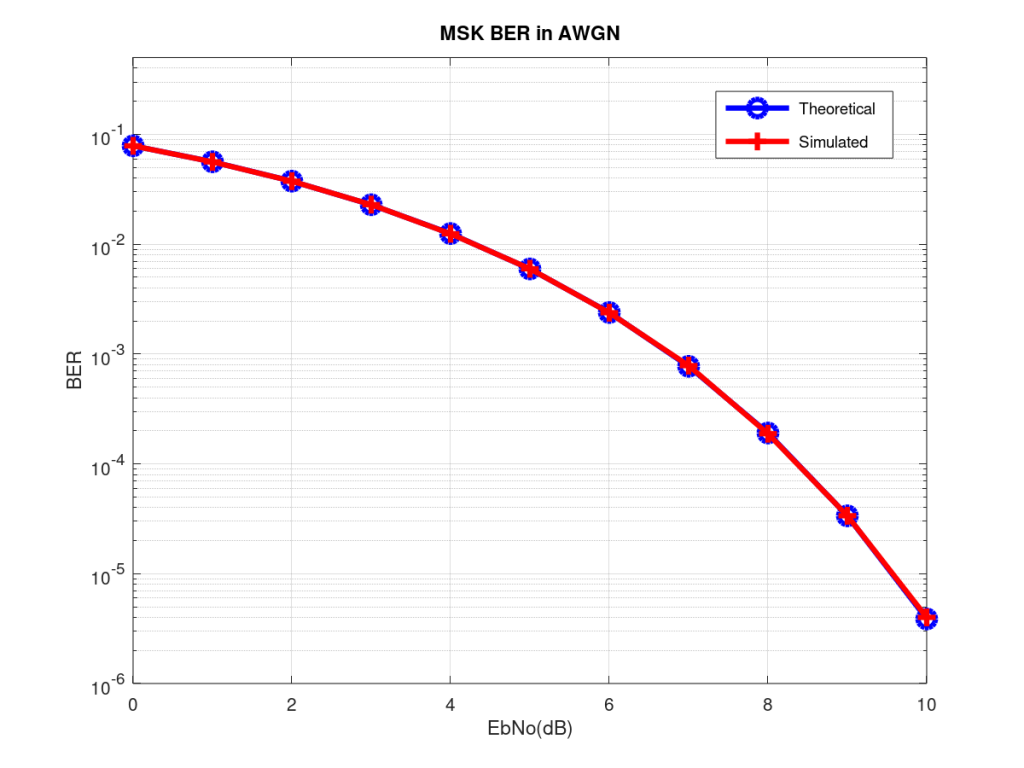
- The BER performance of MSK in AWGN matches exactly with that for BPSK (both theoretical and simulated).
- The number of samples per symbol, in BER simulation, may be varied from four to ten depending upon the accuracy required.
- The BER simulation code given above can be easily modified to handle Rayleigh fading case as well.
- The x-axis of the PSD is the frequency normalized by bit rate, given as Hz/bits/sec.
- We used PWELCH for calculating the PSD of BPSK/QPSK/MSK which is available as part of Signal package in Octave. Directly using FFT is not recommended as there is lot of fluctuation in the frequency domain which makes the comparison a bit difficult.
- Lastly, we would like to point out that it is possible to detect two equal power overlapping MSK signals if they have a π/2 phase shift between them. This will be the subject of a future post.
[1] Principles of Mobile Communication By Gordon L. Stüber
4 thoughts on “MSK – A Continuous Phase Modulation (CPM)”
Great great. Thanks for sharing