Some Background
Before we delve deep into Minimum Shift Keying (MSK) and its performance in presence of co-channel interference the reader is advised to look at the following posts.
Post 1 – MSK BER performance in AWGN and flat fading environment when viewed as extension of BPSK
Post 2 – MSK Power Spectral Density and its BER performance in AWGN when viewed as a CPM
Post 3 – MSK BER Performance in AWGN and flat fading environment when viewed as a CPM
Co-channel interference is a phenomenon widely encountered in wireless communication systems and the main reason for that is frequency reuse, which allows the same frequency band to be used over and over again in geographically non-contiguous areas. GSM and other wireless communication systems, using MSK modulation, suffer from the same problem. This has been widely studied in the literature and interference rejection techniques have been proposed. The worst case is one where the power of both the signals (wanted signal and interference) is almost the same and there is no frequency or phase offset.
What is Orthogonal MSK
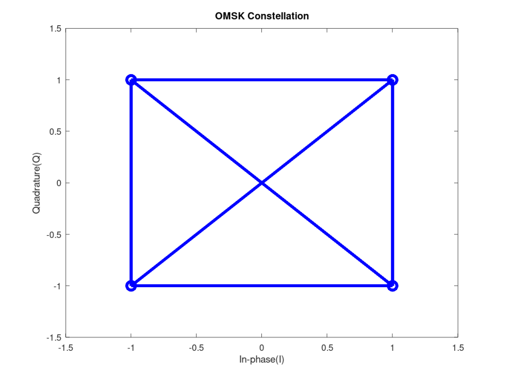
In this post we consider a special case of MSK which we refer to as Orthogonal MSK (OMSK) where the power of both the signals is the same (or almost the same) and there is no frequency offset. However, there is a phase offset of 90 degrees between the signal of interest and interferer. As is evident from our previous posts MSK can be viewed as BPSK with information being transferred via in-phase (I) and quadrature (Q) carriers alternatively. In OMSK the interferer is 90 degrees offset from the signal of interest. So, when there is information being transmitted via I, interferer is on Q and when information is being transmitted via Q, interferer is on I [1].
Simulation Scenario
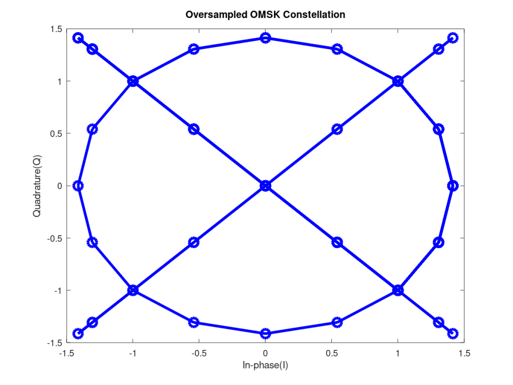
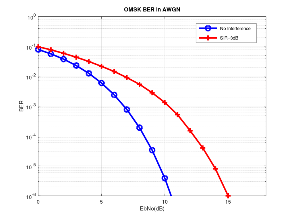
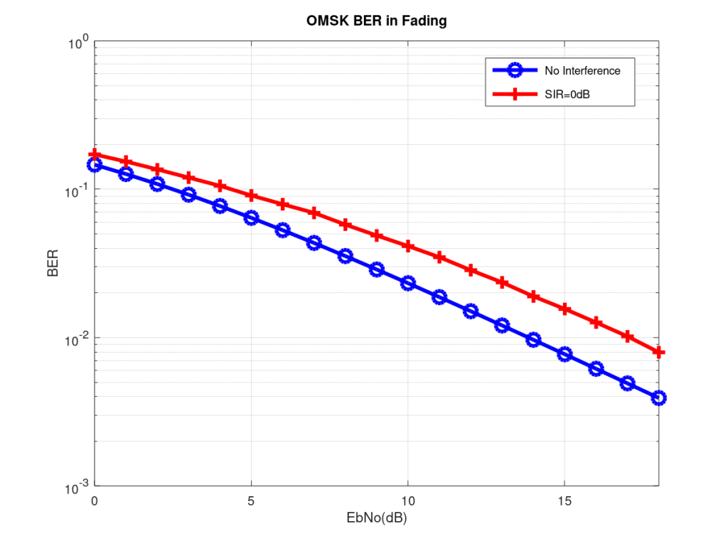
We performed the simulation of this scenario and found that the performance of OMSK in AWGN and fading is exactly the same as MSK/BPSK when we transmit one sample per symbol i.e. there is no over-sampling. However, the orthogonality breaks down when the there are multiple samples per symbol. The reason for this it seems is that the sinusoidal symbol shaping is not continuous and there are discontinuities at the symbol boundaries. But still the performance of OMSK is much better than MSK, without control over relative phase of the interferer, which is usually the case in interference limited environments.
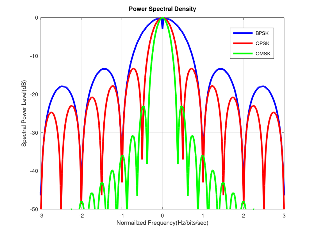
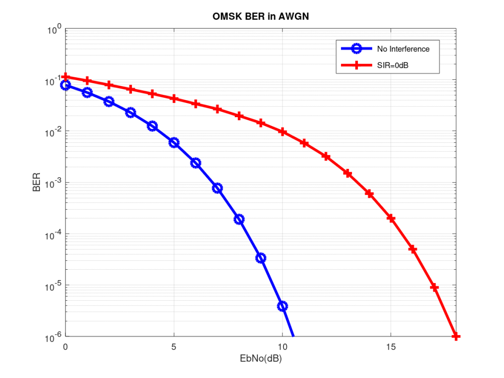
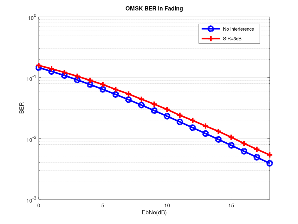
The performance of OMSK greatly improves if there is a small difference between the power levels of the signal of interest and the interferer (such as SIR=3dB). Also, OMSK performance in fading environment is pretty close to pure MSK with no interference. Since we are now transmitting two bits per symbol, we also need to revisit the normalized PSD (normalized by the bit rate). We had previously seen that MSK is better than BPSK but worse than QPSK when we look at the width of the main lobe. But OMSK beats both BPSK and QPSK in this and furthermore its side lobes are much lower. Sidelobes can be further lowered by using a Gaussian filter.
Mathematical Model of OMSK
The mathematical model for the received OMSK signal is shown below. It is seen that we can perform channel equalization by simply dividing the received signal r by the channel coefficient h1 (assuming a flat fading channel which is described by a one tap filter). But it must be noted that although this removes the effect the channel has on the signal of interest, it is not able to remove the effect the channel has on the interferer. For this we have to assume that h1=h2. That is the two signals originate from the same source and undergo similar fading. In future we might dedicate a post to study the degradation in BER performance as correlation between the two channel coefficients decreases.
r=h1*s1+h2*s2+n
r/h1=s1+(h2/h1)*s2+n/h1
In Octave the code for OMSK can be easily derived by modifying the code given in Post 3. The received signal can be obtained using the following piece of code:

rx_signal=ray_chan_vec.*tx_signal;
rx_signal_int=ray_chan_vec.*tx_signal_int;   rx_signal=rx_signal+rx_signal_int*exp(i*pi/2)+sigma*AWGN_noise;

tx_signal_int is the transmitted interferer and is obtained just as you obtained tx_signal.

As can be seen the 90 degree phase shift between the two signals is implemented by multiplying by the interfering term by exp(i*pi/2).
Simulation Results
Note:
- We have ignored pulse shaping here. With ideal pulse shaping the PSD of QPSK improves while its BER remains the same (which is much better than OMSK).
- Gaussian pulse shaping can be used to improve the PSD of MSK/OMSK further but there is a penalty in the BER.
Reference:
[1] Yasir Ahmed, Jeffrey H. Reed, William H. Tranter, R. Michael Buehrer “A Model Based Approach to Demodulation of Co-channel MSK Signals,” Globecom 2003, San Francisco, CA, USA.