
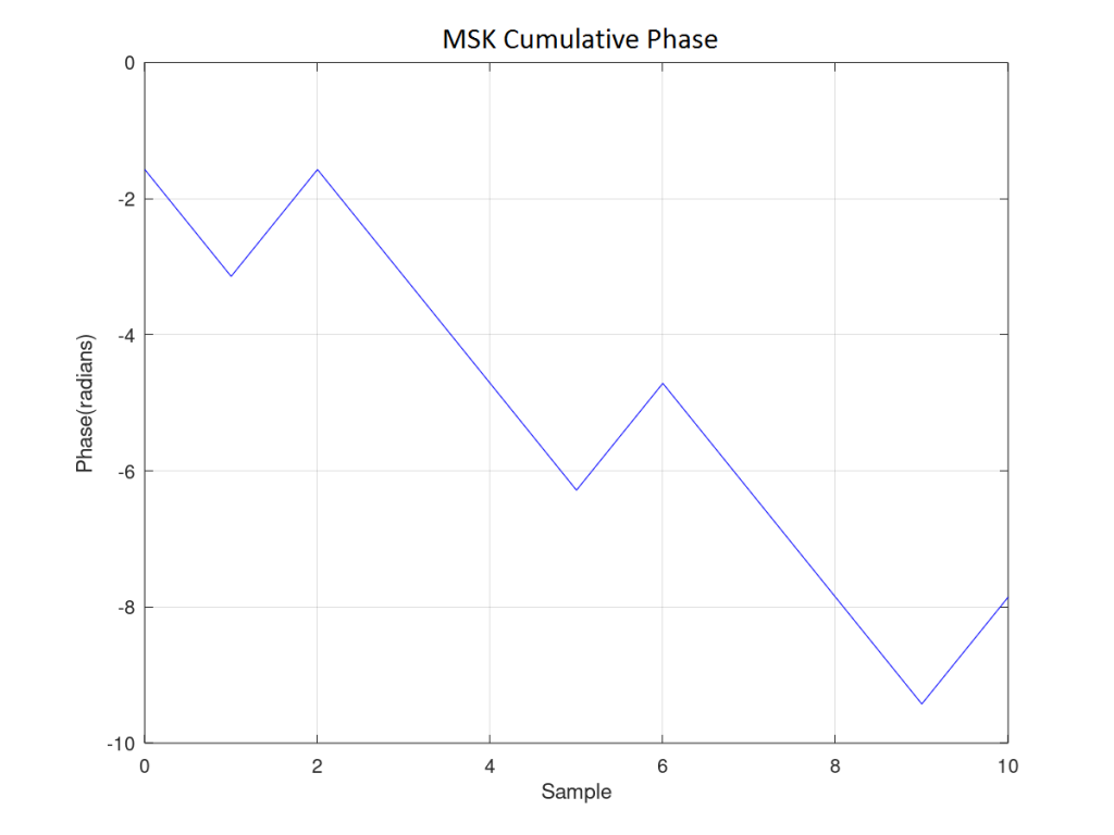
I - Minimum Shift Keying (MSK) is a type of Continuous Phase Modulation (CPM) that has been used in many wireless communication systems. To be more precise it is Continuous Phase Frequency Shift Keying (CPFSK) with two frequencies f1 and f2. The frequency separation between the two tones is the minimum allowable while maintaining orthogonality and is equal to half the bit rate (or symbol rate, as both are the same). The frequency deviation is then given as Δf=Rb/4. The two tones have frequencies of fc±Δf where fc is the carrier frequency. MSK is sometimes also visualized as Offset QPSK (OQPSK) but we will not go into its details here.
II - As is known Continuous Phase Modulations typically have a constant envelope. That is there is no Amplitude Modulation (AM) and the signal is not affected by distortion of carrier amplitude by fading or non-linear amplification. Continuity of phase also means that there are no abrupt changes in phase and sidelobe levels are very low. It must be noted however that in MSK the width of the main lobe is wider than in QPSK (but less than BPSK). The sidelobe level of MSK can be further reduced by using a Gaussian filer. The modulation so obtained is called Gaussian Minimum Shift Keying (GMSK).
III - GMSK modulation was adopted by GSM standard (a 2G standard) but has now gone out of favor as more spectrally efficient waveforms such as OFDM/QAM have taken over. The sidelobe level depends upon the symbol time (T) and bandwidth (B) product which is abbreviated as BT. Smaller the value of BT lower is the sidelobe level. However, lower value of BT means greater Inter-Symbol Interference (ISI) which requires an equalizer such as Decision Feedback Equalizer (DFE). In GSM systems BT was kept at 0.3 whereas in Bluetooth it was 0.5. In this post we consider simple MSK without any filtering. The channel is considered to be AWGN but fading can also be easily introduced.

MATLAB Code
%%%%%%%%%%%%%%%%%%%%%%%%%%%%%%%%%%%%%%%%%%%%%
%           MINIMUM SHIFT  KEYING           %
%            BER OF MSK IN AWGN             %
%             www.raymaps.com               %
%%%%%%%%%%%%%%%%%%%%%%%%%%%%%%%%%%%%%%%%%%%%%
clear all
close all

no_of_bits=5e6;
bits_in=round(rand(1,no_of_bits));
differential_bits=abs(diff([0, bits_in]));
bipolar_symbols=differential_bits*2-1;
cumulative_phase=(pi/2)*cumsum(bipolar_symbols);
tx_signal=exp(i*cumulative_phase);

Eb=1;
EbNodB=10;
EbNo=10^(EbNodB/10);
sigma=sqrt(Eb/(2*EbNo));
AWGN_noise=randn(1,no_of_bits)+i*randn(1,no_of_bits);
rx_signal=tx_signal+sigma*AWGN_noise;

rx_signal(2:2:end)=real(rx_signal(2:2:end));
rx_signal(1:2:end)=imag(rx_signal(1:2:end));

k=1:no_of_bits;
k=round(k/2);
multiplier=(-1).^(k+1);
demodulated_symbols=multiplier.*sign(rx_signal);
bits_out=demodulated_symbols*0.5+0.5;

ber_simulated=sum(bits_out!=bits_in)/no_of_bits
ber_theoretical=0.5*erfc(sqrt(EbNo))
Simulation Results
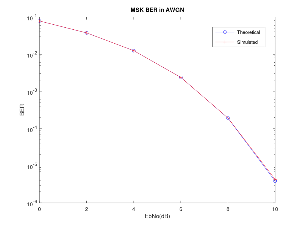
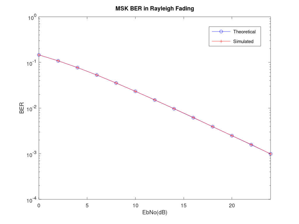
Bit Error Rate (BER) simulation was carried out in MATLAB using one sample per symbol. This is done to keep the processing time to a minimum, however, the reader is encouraged to experiment with multiple samples per symbol. The environment under which the MSK BER is calculated is AWGN. Simulation for a Rayleigh fading channel can be done by adding the following two lines of code:
channel_coeff=(1/sqrt(2))*(randn(1,no_of_bits)+i*randn(1,no_of_bits));
rx_signal=abs(channel_coeff).*tx_signal+sigma*AWGN_noise;
Theoretical BER in Rayleigh fading environment can be calculated as:
ber_theoretical=0.5*(1-sqrt(EbNo/(EbNo+1)))
Theoretical and simulation results for both AWGN and Rayleigh environment match perfectly. It must be noted that BER results for both the environments exactly match with the results for BPSK. This is because both the modulations are essentially binary phase shift modulations, one using only real plane while other using both real and imaginary (alternatively).
4 thoughts on “Minimum Shift Keying Bit Error Rate in AWGN”