
Background
Just like different frequency bands and time slots can be used to multiplex users, spatial domain can also be exploited to achieve the same result. It is well known that if there are 4 transmit antennas and 4 receive antennas then four simultaneous data streams can be transmitted over the air. This can be scaled up to 8 x 8 or in the extreme case to 128 x 128. When the number of transmit or receive antennas is greater than 100 we typically call it a Massive MIMO scenario and we need specialized signal processing techniques to handle this case. Computationally complex techniques like Maximum Likelihood (ML) become quite difficult to implement in real-time and we have to resort to some simplified linear array processing techniques. This is the topic of this blog post.
Description of the Scenario
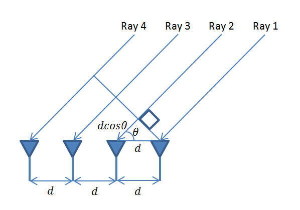
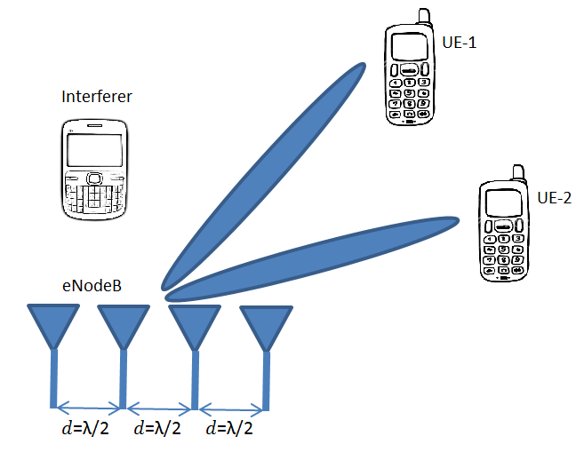
To understand the scenario that we will discuss here, please look at our previous post. Also note that when we talk about nT x nR case we do not necessarily mean nT transmit antennas and nR receive antennas, it could also mean nT users with 1 antenna each and co-located nR receive antennas, such as at a base station. We typically assume that the number of receive antennas is greater than the number of users. When the number of users is greater than the number of receive antennas we call it overloaded case and this is not discussed here. Here the number of users is fixed at 16 (randomly distributed between 0 and 360 degrees within the cell) and the number of receive antennas is varied from 20 to 100.
Linear Signal Processing Techniques for Massive MIMO
The four signal processing techniques that are applied at the receive array are:
- Matched Filtering (MF)
- Moore Penrose Pseudo-Inverse without controlling the threshold (PINV)
- Moore Penrose Pseudo-Inverse with a specified threshold (PINV with tol)
- Minimum Mean Squared Error (MMSE)
Simulation Results
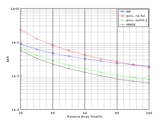
There are some other techniques that we experimented with but are omitted here for the sake of brevity. The MATLAB code and simulation results showing bit error rate as a function of receive array size (nR) are given below. It is seen that simple Matched Filter works quite well when the receive array size is small but with increasing nR the performance improvement is not that great. Least Squares (LS) technique using Moore-Penrose Pseudo Inverse shows improved performance with increasing nR and this can be further improved by controlling the threshold (tol). We found that a threshold of 0.1 gave significantly improved results as compared to no threshold case. Lastly we implemented MMSE and found that it gave us the best results. It must be noted that we also implemented ML for a limited size of receive array and found that its BER performance was far superior than any other technique.
MATLAB Code for Massive MIMO Scenario
%%%%%%%%%%%%%%%%%%%%%%%%%%%%%%%%%%%%
% MASSIVE MIMO BEAMFORMING
% COPYRIGHT RAYMAPS (C) 2018
%%%%%%%%%%%%%%%%%%%%%%%%%%%%%%%%%%%%

clear all
close all

% SETTING THE PARAMETERS FOR THE SIMULATION
f=1e9;        %Carrier frequency
c=3e8;        %Speed of light
l=c/f;        %Wavelength
d=l/2;        %Rx array spacing
N=20;         %Receive array size
M=16;         %Transmit array size (users)
theta=2*pi*(rand(1,M));         %Angular separation of users
EbNo=10;                        %Energy per bit to noise PSD
sigma=1/sqrt(2*EbNo);           %Standard deviation of noise

n=1:N;                          %Rx array number
n=transpose(n);                 %Row vector to column vector

% RECEIVE SIGNAL MODEL (LINEAR)
s=2*(round(rand(M,1))-0.5);           %BPSK signal of length M
H=exp(-i*(n-1)*2*pi*d*cos(theta)/l);  %Channel matrix of size NxM
wn=sigma*(randn(N,1)+i*randn(N,1));   %AWGN noise of length N
x=H*s+wn;                             %Receive vector of length N

% LINEAR ARRAY PROCESSING - METHODS
% 1-MATCHED FILTER
y=H'*x;

% 2-PINV without tol
% y=pinv(H)*x;

% 3-PINV with tol
% y=pinv(H,0.1)*x;

% 4-Minimum Mean Square Error (MMMSE)
% y=(H'*H+(2*sigma^2)*eye([M,M]))^(-1)*(H')*x;

% DEMODULATION AND BER CALCULATION
s_est=sign(real(y));          %Demodulation
ber=sum(s!=s_est)/length(s);  %BER calculation

%Note: Please select the array processing technique
%you want to implement (1-MF, 2-LS1, 3-LS2, 4-MMSE)
Note:
- In the code above, N=nR and M=nT
- What is labelled here as Matched Filter (MF) is strictly speaking Maximal Ratio Combining (MRC)
- The case we discuss above is categorized as Multiuser MIMO (MU-MIMO) for the uplink
- MU-MIMO for the downlink is not that straight forward and will be the subject of some future post
- We have considered a deterministic channel model as opposed to a probabilistic channel model
- Probabilistic channel model can be easily implemented by assuming that channel coefficients are independent and identically distributed (IID) complex Gaussian random variables with mean zero and variance of 0.5 per dimension
- The initial results we have obtained using this probabilistic channel model are much better than the results shown above, but the question remains which is the more accurate representation of a real channel
Update: Simulation Using a Probabilistic Channel
Since most of the literature in Massive MIMO uses a probabilistic channel instead of a deterministic channel, we decided to investigate this further. To implement such a channel model we simply need to change one line of the MATLAB code shown above. Instead of defining H as:
H=exp(-i*(n-1)*2*pi*d*cos(theta)/l);
We define H as:
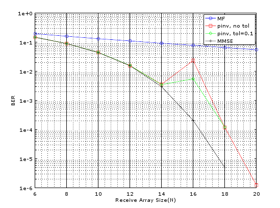
H=(1/sqrt(2))*randn(N,M)+i*(1/sqrt(2))*randn(N,M);
The results are shown below. It is seen that the BER performance is orders of magnitude better. We would next investigate the performance degradation if the channel coefficients are not independent and identically distributed (IID) but have some correlation. This is closely tied to inter-element separation of the antenna array.
Concluding Remarks
The fundamental question that needs to be asked is why the performance in the NLOS scenario (probabilistic) is better than LOS scenario (deterministic). This has to do with the Signal to Noise Ratio [1]. In the above we have assumed the Signal to Noise Ratio (SNR) for the two scenarios to be the same. But realistically speaking this is never the case. Although the NLOS case assumes a rich scattering environment providing a high multiplexing gain (dependent on the rank of the channel matrix H) its SNR would always be lower due to reflection, diffraction and scattering loss. So a fair comparison between the LOS and NLOS case is only possible if we downward adjust the SNR for the NLOS case. Simulation results have shown that the SNR for the NLOS case needs to be downgraded by about 25 dB to have similar BER performance as the LOS case. Lastly it must be noted that the BER performance of the NLOS case would deteriorate once the channel coefficients are not IID and there is some correlation between them.
[1] Zimu Cheng, Binghao Chen, and Zhangdui Zhong “A Tradeoff between Rich Multipath and High Receive Power in MIMO Capacity”, International Journal of Antennas and Propagation, Volume 2013.
Author: Yasir
More than 25 years of experience in various organizations in Pakistan, the USA, and Europe. Worked with the Mobile and Portable Radio Group (MPRG) of Virginia Tech and Qualcomm USA and was one of the first researchers to propose Space Time Block Codes for eight transmit antennas. Had the opportunity to work with world renowned wireless experts such as Dr. Ted Rappaport, and Dr. Jeffrey H. Reed. Have published a book “Recipes for Communication and Signal Processing” through Springer Nature.
17 thoughts on “Massive MIMO Fundamentals and Code”
Thank you dear John. I changed the code as you instructed i.e.,
%%%%%%%%%%%%%%%%%%%%%%%%%%%%%%%%%%%%
% BEAMFORMING USING A
% UNIFORM LINEAR ARRRAY
% COPYRIGHT RAYMAPS (C) 2018
%%%%%%%%%%%%%%%%%%%%%%%%%%%%%%%%%%%%
clear all
close all
f=1e9;
c=3e8;
l=c/f;
d=l/2;
no_elements=10;
% phi=pi/6;
phi=0:pi/360:2*pi;
% theta=0:pi/180:2*pi;
theta=pi/180;
n=1:no_elements;
n=transpose(n);
X=exp(-i*(n-1)*2*pi*d*cos(theta)/l);
w=exp( i*(n-1)*2*pi*d*cos(phi)/l);
w=transpose(w);
r=w*X;
polar(phi,abs(r),’b’)
title (‘Gain of a Uniform Linear Array’)
But now it gives the following error:
Error using polar (line 65)
THETA and RHO must be the same size.
Error in raymapcode (line 28)
polar(phi,abs(r),’b’)
I am not getting any error in Octave but it could be that you are getting an error because one is a row vector and one is a column vector. Just use transpose to fix that.
Also, try different values of theta such as:
theta=0*pi/180
theta=45*pi/180
theta=90*pi/180
See how the polar plot changes. Basically you are changing the direction of the arriving wave.
Hi dear John!
Your code gives BER vs Receiver Array size. But if I am interested in DOAs and DODs of the multipaths of the users instead of the BER, then what should I do? If you guide me a little bit in MATLAB with comments as I am not so much expert in MATLAB, I will be obliged.
Regards,
I am no expert but will try to help a little bit. Angle of Arrival (AoA) can be measured by two simple methods.
1. Rotate the array 360 degrees and find the angle where received signal strength at broadside is maximum.
2. Measure the difference in angle between two adjacent sensor elements and this should give you the direction of incoming wave e.g. if the signals are arriving from broadside difference would be zero.
More complex systems use High Resolution Spectral Estimation techniques such as MUSIC and ESPRIT.
Thank you very much dear John for your response. Can you guide me further where should I rotate the array in your above code for finding the angle of the received signal? I don’t see any array in it.
Look at the following post.
http://www.raymaps.com/index.php/basics-of-beam-forming-in-wireless-communications/
Instead of varying theta change phi and observe the behavior.
Thank you dear John for your guidance. I changed according to your instruction as below and ran it:
%%%%%%%%%%%%%%%%%%%%%%%%%%%%%%%%%%%%
% BEAMFORMING USING A
% UNIFORM LINEAR ARRRAY
% COPYRIGHT RAYMAPS (C) 2018
%%%%%%%%%%%%%%%%%%%%%%%%%%%%%%%%%%%%
clear all
close all
f=1e9;
c=3e8;
l=c/f;
d=l/2;
no_elements=10;
% phi=pi/6;
phi=0:pi/360:2*pi;
% theta=0:pi/180:2*pi;
theta=pi/180;
n=1:no_elements;
n=transpose(n);
X=exp(-i*(n-1)*2*pi*d*cos(theta)/l);
w=exp( i*(n-1)*2*pi*d*cos(phi)/l);
w=transpose(w);
r=w*X;
polar(theta,abs(r),’b’)
title (‘Gain of a Uniform Linear Array’)
But it gives me the following error:
Error using polar (line 65)
THETA and RHO must be the same size.
Error in raymapcode (line 28)
polar(theta,abs(r),’b’)
Try this:
polar(phi,abs(r),’b’)
Also, need to define phi and theta properly.
Dear John the figure that I get with your code is different from those you have given here.
How can we get figures like yours. Further, in your figures, there are multiple plots but in mine I have only one plot.
You can get one plot at a time. Select a technique (uncomment) and see the results. I usually only give the core algorithms. Have to do a bit of work to get the plots.
There is no command which shows the plot, I am new to Matlab as well , how do I plot the different values of N (receive array)and BER?
plotting (N,ber) doesn’t fetch me anything, could you please provide the plot commands?
clear all %Clear all variables
close all %Close all figures
N_vector=20:20:100; %Rx array length range
for j=1:length(N_vector)%Varying the length of the receive array
N=N_vector(j); %Selecting a value of N
for k=1:50000 %This number may be increased
Massive_MIMO1; %This should be the same as the name of main file
BER_array(k)=ber; %Storing the BER in the array
end
BER_total(j)=mean(BER_array) %Calculating the mean BER for each N
end
semilogy(N_vector, BER_total,’ro-‘) %Plot on log scale
xlabel(‘Receive Array Size(N)’) %X-label
ylabel(‘BER’) %Y-label
hold on %Hold on
grid on %Grid on
Although I do not like to give the complete code but I am breaking the rules and giving it to you above 🙂
Please remember the following while using the code:
1. Comment out N=20 (put % before the line) from the main code since this new file is going to provide values of N
2. Comment out “clear all” and “close all” from the main code since this is taken care of in this new wrapper file
3. Save the main file as Massive_MIMO1.m
4. Save the wrapper file as BER_Wrapper1.m
Hope it works!
Dear Sir,
I get the following error at line
H=exp(-i*(n-1)*2*pi*d*cos(theta)/l);
Error using *
Incorrect dimensions for matrix multiplication. Check that the number of columns in the first matrix matches the number of rows in the second matrix. To perform elementwise multiplication, use ‘.*’.
I hope you copy pasted the whole code and not just this one line. Try it again and let me know. This has been tested by me several times.
Dear Sir ,
I get an error when i run the first code with probabailistic channel H=exp(-i*(n-1)*2*pi*d*cos(theta)/l);
could you please tell me what could be wrong .
the code stops at this line ‘H’ and says
H=exp(-i*(n-1)*2*pi*d*cos(theta)/l);
Error using *
Incorrect dimensions for matrix multiplication. Check that the number of columns in the first matrix matches the number of rows in the second matrix. To perform elementwise multiplication, use ‘.*’.
i used the exact code to check what i can see.