Category Archives: WiMAX

Propagation and In-Building Penetration at 700MHz

It is quite well known that wireless signals travel further at lower frequencies. This phenomenon has become particularly important in the context of LTE where a frequency band has been allocated at 700MHz. We would like to quantify the benefits that can be achieved by using this frequency band.

Firstly we find the received signal power at 728 MHz (lowest downlink frequency) and at 3600 MHz (highest downlink frequency) in a free space line of sight channel. The transmit power is set to 1 W and omnidirectional antennas are considered at the transmitter and receiver. The received power for these two frequencies at a distance of 1000 m is found out to be -59.68dBm and -73.57dBm respectively i.e. there is a gain of 13.88 dB by using the lower frequency band. In simpler terms the signal power would be more than 20 times stronger at the lower frequency. This result can also be simply obtained by taking the square of the ratio the two frequencies.

(3600/728)^2 = 24.45

Similarly compared to a frequency of 1805 MHz, the signal at 728 MHz would be more than 6 times stronger.

(1805/728)^2 = 6.1474

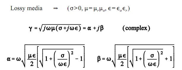
Now we turn our attention to the penetration loss i.e. how much would the signal attenuate when passing through a concrete wall. For this we would have to calculate the attenuation constant (alpha) which is given as:

Attenuation Constant
Propagation Constant

Alpha, the attenuation constant is the real part of the propagation constant gamma whereas Beta, the phase constant, is the imaginary part. These quantities depend upon the frequency, relative permittivity, relative permeability and conductivity of the material. The penetration loss can then be found as -20*log10(exp(-alpha*thickness)). Using the properties of concrete the penetration loss at 728 MHz and at 1805 MHz is found out to be 4.16 dB and 10.38 dB i.e. there is a gain of 6.22 dB when using the lower frequency. In simpler terms the signal at the lower frequency would be more than 4 times stronger. We have considered a concrete wall of 10 cm thickness.

It is quite evident that the frequency of operation plays a big role in determining the propagation loss and the penetration loss. The frequency band of 728-746 MHz would thus be a prized commodity and operators would be willing to pay handsome amount to secure it.

Note:

1. We have ignored the reflection that occurs at the interface as its effect is comparably quite small.

2. Following were the material properties of concrete used in the calculation for penetration loss.

728 MHz
Relative permittivity = 4.5775
Relative permeability = 1.0000
Conductivity = 0.055

1805 MHz
Relative permittivity = 4.1000
Relative permeability = 1.0000
Conductivity = 0.1300
BER of 64-QAM OFDM in Frequency Selective Fading-II

In the previous post we had considered a static frequency-selective channel. We now consider a time-varying frequency selective channel with 7 taps. Each tap of the time domain filter has a Gaussian distributed real component with variance 1/(2*n_tap) and a Gaussian distributed imaginary component with variance 1/(2*n_tap). The amplitude of each tap is thus Rayleigh distributed and the phase is Uniformly distributed. Since the power in each component is normalized by the filter length (n_tap) the BER performance would remain the same even if the filter length is changed (this has been verified experimentally).

%%%%%%%%%%%%%%%%%%%%%%%%%%%%%%%%%%%%%%%%%%%%%%%%%%%%%%%%%%%%%%%%%%%%%%%%%
% FUNCTION TO SIMULATE PERFORMANCE OF 64-OFDM IN TIME VARYING FREQUENCY SELECTIVE CHANNEL
% n_bits: Input, length of binary sequence
% n_fft: Input, length of FFT (Fast Fourier Transform)
% EbNodB: Input, energy per bit to noise power spectral density ratio
% ber: Output, bit error rate
% Copyright RAYmaps (www.raymaps.com)
%%%%%%%%%%%%%%%%%%%%%%%%%%%%%%%%%%%%%%%%%%%%%%%%%%%%%%%%%%%%%%%%%%%%%%%%%
function[ber]= M_QAM_OFDM_fading(n_bits,n_fft,EbNodB)

Eb=7;
M=64;
k=log2(M);
n_cyc=32;
EbNo=10^(EbNodB/10);
x=transpose(round(rand(1,n_bits)));
h1=modem.qammod(M);
h1.inputtype='bit';
h1.symbolorder='gray';
y=modulate(h1,x);
n_sym=length(y)/n_fft;
n_tap=7;

for n=1:n_sym;
    s_ofdm=sqrt(n_fft)*ifft(y((n-1)*n_fft+1:n*n_fft),n_fft);
    s_ofdm_cyc=[s_ofdm(n_fft-n_cyc+1:n_fft); s_ofdm];
    ht=(1/sqrt(2))*(1/sqrt(n_tap))*(randn(1,n_tap)+j*randn(1,n_tap));
    Hf=fft(ht,n_fft);
    r_ofdm_cyc=conv(s_ofdm_cyc,ht);
    r_ofdm_cyc=(r_ofdm_cyc(1:n_fft+n_cyc));
    wn=sqrt((n_fft+n_cyc)/n_fft)*(randn(1,n_fft+n_cyc)+j*randn(1,n_fft+n_cyc));
    r_ofdm_cyc=r_ofdm_cyc+sqrt(Eb/(2*EbNo))*wn.';
    r_ofdm=r_ofdm_cyc(n_cyc+1:n_fft+n_cyc);
    s_est((n-1)*n_fft+1:n*n_fft)=(fft(r_ofdm,n_fft)/sqrt(n_fft))./Hf.';
end

h2=modem.qamdemod(M);
h2.outputtype='bit';
h2.symbolorder='gray';
h2.decisiontype='hard decision';
z=demodulate(h2,s_est.');
ber=(n_bits-sum(x==z))/n_bits
return
%%%%%%%%%%%%%%%%%%%%%%%%%%%%%%%%%%%%%%%%%%%%%%%%%%%%%%%%%%%%%%%%%%%%%%%%%

As before we have used an FFT size of 128 and cyclic prefix of 32 samples. The FFT and IIFT operations are normalized to maintain the signal to noise ratio (SNR). The extra energy transmitted in the cyclic prefix is also accounted for in the SNR calibration.

64-QAM BER in Time Varying Frequency Selective Channel

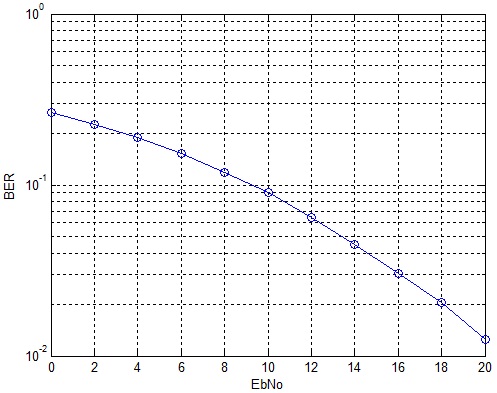
It is observed that the BER performance of 64-QAM OFDM in the time-varying frequency-selective channel is quite similar to that in the static frequency-selective channel with complex filter taps. It must be noted that with 64-QAM the goal is to achieve higher bit rate, error rates can be improved using antenna diversity and channel coding schemes.

Given below is the wrapper that should be used along with the above code. The wrapper basically calls the above routine for each value of EbNodB. The length of the binary sequence and the FFT size are other inputs to the function. The bit error rate at the specific EbNodB is the output of the function.

%%%%%%%%%%%%%%%%%%%%%%%%%%%%%%%%%%%
clear all;
close all;
k=6;
n_fft=128;
l=k*n_fft*1e3;
EbNodB=0:2:20;
for n=1:length(EbNodB);n
ber(n)=M_QAM_OFDM_fading(l,n_fft,EbNodB(n));
end;
semilogy(EbNodB,ber,'O-');
grid on
xlabel('EbNo')
ylabel('BER')
%%%%%%%%%%%%%%%%%%%%%%%%%%%%%%%%%%%

In future we would use the standard LTE channel models, namely EPA, EVA and ETU in our simulation.

BER of 64-QAM OFDM in Frequency Selective Fading

The real benefits of OFDM become apparent in a frequency selective channel. The introduction of the cyclic prefix (guard period) allows us to remove the Intersymbol Interference (ISI) in the time domain and frequency domain equalization allows us to overcome the channel variations in the frequency domain.

We consider a simple FIR filter for our channel model with coefficients ht=[0.8 0.54 0.24 0.10 0.04]. This is a simplistic approach since the channel coefficients are all real which means that all multipath components are co-phase. To model a more realistic channel we then introduce a uniform phase shift to all the channel coefficients.

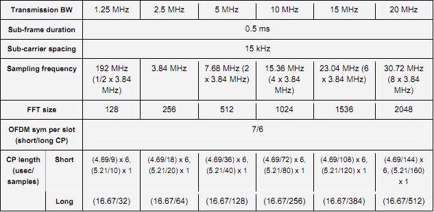
LTE Physical Layer Parameters

We use an FFT size of 128 and cyclic prefix of 32 samples (16.67usec) in the simulation given below.

%%%%%%%%%%%%%%%%%%%%%%%%%%%%%%%%%%%%%%%%%%%%%%%%%%%%%%%%%%%%%%%%%%%%%%%%%
% FUNCTION TO SIMULATE THE PERFORMANCE OF 64-QAM OFDM IN STATIC FREQUENCY SELECTIVE CHANNEL
% n_bits: Input, length of binary sequence
% n_fft: Input, length of FFT (Fast Fourier Transform)
% EbNodB: Input, energy per bit to noise power spectral density ratio
% ber: Output, bit error rate
% Copyright RAYmaps (www.raymaps.com)
%%%%%%%%%%%%%%%%%%%%%%%%%%%%%%%%%%%%%%%%%%%%%%%%%%%%%%%%%%%%%%%%%%%%%%%%%
function[ber]= M_QAM_OFDM_fading(n_bits,n_fft,EbNodB)

Eb=7;
M=64;
k=log2(M);
n_cyc=32;
EbNo=10^(EbNodB/10);
x=transpose(round(rand(1,n_bits)));
h1=modem.qammod(M);
h1.inputtype='bit';
h1.symbolorder='gray';
y=modulate(h1,x);
n_sym=length(y)/n_fft;

for n=1:n_sym;
    s_ofdm=sqrt(n_fft)*ifft(y((n-1)*n_fft+1:n*n_fft),n_fft);
    s_ofdm_cyc=[s_ofdm(n_fft-n_cyc+1:n_fft); s_ofdm];
    ht=[0.8 0.54 0.24 0.10 0.04];
    Hf=fft(ht,n_fft);
    r_ofdm_cyc=conv(s_ofdm_cyc,ht);
    r_ofdm_cyc=(r_ofdm_cyc(1:n_fft+n_cyc));
    wn=sqrt((n_fft+n_cyc)/n_fft)*(randn(1,n_fft+n_cyc)+j*randn(1,n_fft+n_cyc));
    r_ofdm_cyc=r_ofdm_cyc+sqrt(Eb/(2*EbNo))*wn.';
    r_ofdm=r_ofdm_cyc(n_cyc+1:n_fft+n_cyc);
    s_est((n-1)*n_fft+1:n*n_fft)=(fft(r_ofdm,n_fft)/sqrt(n_fft))./Hf.';
end

h2=modem.qamdemod(M);
h2.outputtype='bit';
h2.symbolorder='gray';
h2.decisiontype='hard decision';
z=demodulate(h2,s_est.');
ber=(n_bits-sum(x==z))/n_bits
return
%%%%%%%%%%%%%%%%%%%%%%%%%%%%%%%%%%%%%%%%%%%%%%%%%%%%%%%%%%%%%%%%%%%%%%%%%

We also have accounted for the extra energy transmitted for the cyclic prefix in our signal to noise calibration.

64-QAM OFDM BER
64-QAM OFDM BER

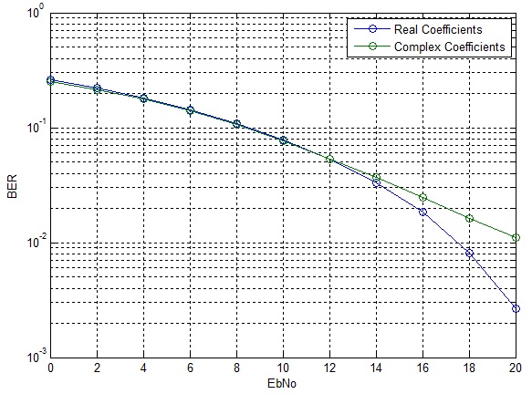
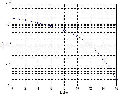
It can be seen that up to 12dB the BER performance for the two cases is quite similar, however, after 12dB the BER for the real case drops significantly whereas the BER for the complex case goes down in linear fashion. The error rate can be significantly improved by employing channel coding and antenna diversity schemes.

BER of 64-QAM OFDM in AWGN

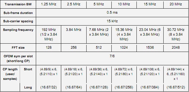
64-QAM is an important component of the LTE Air Interface that promises higher data rates and spectral efficiencies. Combined with OFDM and MIMO it successfully combats the detrimental effects of the wireless channels and provides data rates in excess of 100Mbps (peak data rate). Here, we discuss a simple example of 64-QAM modulation with OFDM in an AWGN channel. We assume a bandwidth of 1.25MHz which corresponds to an FFT size of 128.

LTE Bandwidth
LTE Bandwidth

Given below is the code for this scheme.

%%%%%%%%%%%%%%%%%%%%%%%%%%%%%%%%%%%%%%%%%%%%%%%%%%%%%%%%%%
% FUNCTION TO CALCULATE BER OF 64-QAM OFDM IN AWGN
% n_bits: Input, number of bits
% n_fft: Input, FFT size 
% EbNodB: Input, energy per bit to noise PSD
% ber: Output, bit error rate
% Copyright RAYmaps (www.raymaps.com)
%%%%%%%%%%%%%%%%%%%%%%%%%%%%%%%%%%%%%%%%%%%%%%%%%%%%%%%%%%
function[ber]= M_QAM(n_bits,n_fft,EbNodB);
Eb=7;
M=64;
k=log2(M);
EbNo=10^(EbNodB/10);
x=transpose(round(rand(1,n_bits)));
h1=modem.qammod(M);
h1.inputtype='bit';
h1.symbolorder='gray';
y=modulate(h1,x);
n_sym=length(y)/n_fft;
s_ofdm=zeros(1,n_fft);
r_ofdm=zeros(1,n_fft);
for n=1:n_sym;
s_ofdm=sqrt(n_fft)*ifft(y((n-1)*n_fft+1:n*n_fft),n_fft);
wn=randn(1,n_fft)+j*randn(1,n_fft);
r_ofdm=s_ofdm+sqrt(Eb/(2*EbNo))*wn.';
s_est((n-1)*n_fft+1:n*n_fft)=fft(r_ofdm,n_fft)/sqrt(n_fft);
end
h2=modem.qamdemod(M);
h2.outputtype='bit';
h2.symbolorder='gray';
h2.decisiontype='hard decision';
z=demodulate(h2,s_est.');
ber=(n_bits-sum(x==z))/n_bits;
return
%%%%%%%%%%%%%%%%%%%%%%%%%%%%%%%%%%%%%%%%%%%%%%%%%%%%%%%%%%

As discussed previously, with proper normalization of IFFT and FFT operations the performance of OFDM in AWGN is the same as the performance of the underlying modulation scheme. We have not even introduced the cyclic prefix in our simulation because without a fading channel there is no ISI and cyclic prefix (CP) is of no use. We will introduce the CP when we turn our attention to fading channels.

OFDM 64-QAM
OFDM 64-QAM

It must be noted that although IFFT and FFT are linear inverses of each other proper normalization is required to maintain the signal levels at the transmitter and receiver.

Bit Error Rate of 64-QAM in AWGN

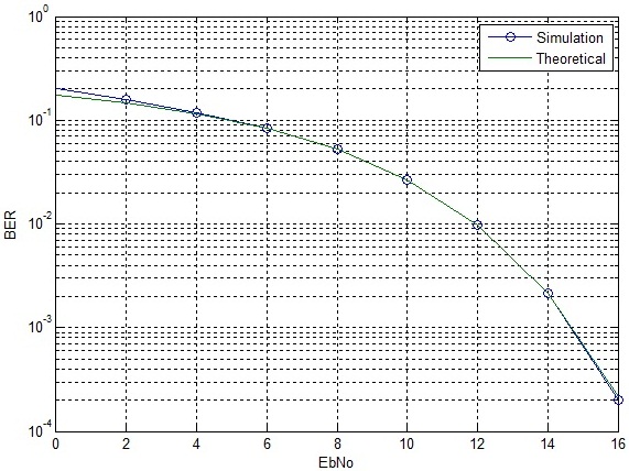
64-QAM is an important modulation scheme being used in WiMAX and LTE. It allows for transmission of 6 bits symbol which results in higher bit rate and spectral efficiency. The calculation of bit error rate of 64-QAM is a bit tricky as there are many different formulas available with varying degrees of accuracy. Here, we first calculate the bit error rate (BER) of 64-QAM using a simulation and then compare it to the theoretical curve for 64-QAM.

%%%%%%%%%%%%%%%%%%%%%%%%%%%%%%%%%%%%%%%%%%%%%%%%%%%%%%
% FUNCTION TO CALCULATE 64-QAM BER USING SIMULATION
% n_bits: Input, number of bits
% EbNodB: Input, energy per bit to noise PSD
% ber: Output, bit error rate
% Copyright RAYmaps (www.raymaps.com)
%%%%%%%%%%%%%%%%%%%%%%%%%%%%%%%%%%%%%%%%%%%%%%%%%%%%%%
function[ber]= M_QAM(n_bits,EbNodB);
M=64;
k=log2(M)
EbNo=10^(EbNodB/10);
x=transpose(round(rand(1,n_bits)));
h1=modem.qammod(M);
h1.inputtype='bit';
h1.symbolorder='gray';
y=modulate(h1,x);
n=randn(1,n_bits/k)+j*randn(1,n_bits/k);
y=y+sqrt(7/(2*EbNo))*n.';
h2=modem.qamdemod(M)
h2.outputtype='bit';
h2.symbolorder='gray';
h2.decisiontype='hard decision';
z=demodulate(h2,y);
ber=(n_bits-sum(x==z))/n_bits
return
%%%%%%%%%%%%%%%%%%%%%%%%%%%%%%%%%%%%%%%%%%%%%%%%%%%%%%
%%%%%%%%%%%%%%%%%%%%%%%%%%%%%%%%%%%%%%%%%%%%%%%%%
% CALCULATE 64-QAM BER USING FORMULA
%%%%%%%%%%%%%%%%%%%%%%%%%%%%%%%%%%%%%%%%%%%%%%%%%
EbNodB=0:2:16;
EbNo=10.^(EbNodB/10);
k=6;
M=64;
x=sqrt(3*k*EbNo/(M-1));
Pb=(4/k)*(1-1/sqrt(M))*(1/2)*erfc(x/sqrt(2));
semilogy(EbNodB,Pb)
%%%%%%%%%%%%%%%%%%%%%%%%%%%%%%%%%%%%%%%%%%%%%%%%%

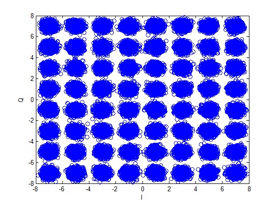
Using the above functions the BER of 64-QAM is calculated as shown below. Also shown is the constellation diagram of 64-QAM after addition of noise.

64-QAM Constellation

64-QAM BER
64-QAM BER

It is observed that the theoretical curve almost overlaps the simulation results. There is only a very small difference at very low signal to noise ratio. The BER of 64-QAM at 16dB is approximately equal to the BER for QPSK at 8dB. Therefore the 64-QAM can only be used in scenarios where there is a very good signal to noise ratio.

In this post we have used built in MATLAB functions for modulation and demodulation. In future posts we try to build up the simulation without using these functions!

OFDM Modulation and Demodulation (AWGN) – II

We have previously looked at a simple OFDM modulation and demodulation scheme. We saw that the BER performance of OFDM in AWGN was the same as the BER performance of the underlying modulation scheme (QPSK in this case). We will now continuously improve upon our basic simulation to get a more realistic picture. In this regard we introduce the cyclic prefix which is used in OFDM to overcome Intersymbol Interference. The duration of the cyclic prefix is 0.8usec (16 samples at 20MHz) resulting in a symbol duration of 4usec (IEEE 802.11a). Given below is the code for OFDM modulation and demodulation with cyclic prefix.

%%%%%%%%%%%%%%%%%%%%%%%%%%%%%%%%%%%%%%%%%%%%%%%%%%%%%%%%%%
% FUNCTION TO CALCULATE BER OF OFDM IN AWGN
% seq_len: Input, number of OFDM symbols
% n_carr: Input, number of subcarriers 
% EbNo: Input, energy per bit to noise PSD
% ber: Output, bit error rate
% Copyright RAYmaps (www.raymaps.com)
%%%%%%%%%%%%%%%%%%%%%%%%%%%%%%%%%%%%%%%%%%%%%%%%%%%%%%%%%%
function[ber]=OFDM_err(seq_len,n_carr,EbNo)
n_pre=16;                                                             
n_tot=n_carr+n_pre;                                                   
for n=1:seq_len
si=2*(round(rand(1,n_carr))-0.5);                                     
sq=2*(round(rand(1,n_carr))-0.5);                                              
s=si+j*sq;                                                            
s_ofdm=sqrt(n_carr)*ifft(s,n_carr);                                   
s_cyc=sqrt(n_carr/n_tot)*([s_ofdm(49:64),s_ofdm]);                    
wn=(1/sqrt(2*10^(EbNo/10)))*(randn(1,n_tot)+j*randn(1,n_tot));        
r=s_cyc+wn;                                                           
r_ext=r(17:80);                                                       
s_est=fft(r_ext,n_carr);                                              
si_est=sign(real(s_est));                                             
sq_est=sign(imag(s_est));                                             
ber1(n)=(n_carr-sum(si==si_est))/n_carr;                              
ber2(n)=(n_carr-sum(sq==sq_est))/n_carr;                               
end
ber=mean([ber1 ber2]);                                                
return
%%%%%%%%%%%%%%%%%%%%%%%%%%%%%%%%%%%%%%%%%%%%%%%%%%%%%%%%%%

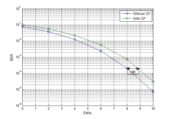
Since the number of samples is increased from 64 to 80 their is an increase in symbol energy. Therefore the signal level needs to be scaled by a factor of sqrt(64/80) to keep the total symbol energy to be the same. This results in approximately 1dB of loss in BER performance as shown in the figure below.

OFDM BER