Category Archives: BER Performance

Bit Error Rate performance as a function of Signal to Noise Ratio.

BER of 64-QAM OFDM in Frequency Selective Fading

The real benefits of OFDM become apparent in a frequency selective channel. The introduction of the cyclic prefix (guard period) allows us to remove the Intersymbol Interference (ISI) in the time domain and frequency domain equalization allows us to overcome the channel variations in the frequency domain.

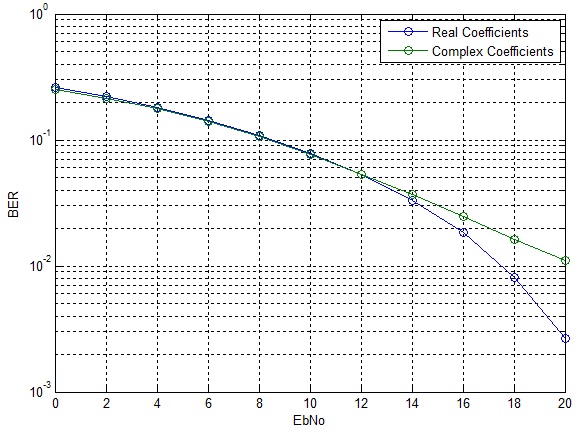
We consider a simple FIR filter for our channel model with coefficients ht=[0.8 0.54 0.24 0.10 0.04]. This is a simplistic approach since the channel coefficients are all real which means that all multipath components are co-phase. To model a more realistic channel we then introduce a uniform phase shift to all the channel coefficients.
LTE Physical Layer Parameters

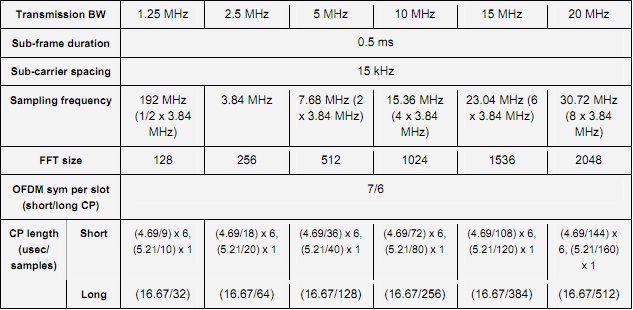
We use an FFT size of 128 and cyclic prefix of 32 samples (16.67usec) in the simulation given below.

%%%%%%%%%%%%%%%%%%%%%%%%%%%%%%%%%%%%%%%%%%%%%%%%%%%%%%%%%%%%%%%%%%%%%%%%%
% FUNCTION TO SIMULATE THE PERFORMANCE OF 64-QAM OFDM IN STATIC FREQUENCY SELECTIVE CHANNEL
% n_bits: Input, length of binary sequence
% n_fft: Input, length of FFT (Fast Fourier Transform)
% EbNodB: Input, energy per bit to noise power spectral density ratio
% ber: Output, bit error rate
% Copyright RAYmaps (www.raymaps.com)
%%%%%%%%%%%%%%%%%%%%%%%%%%%%%%%%%%%%%%%%%%%%%%%%%%%%%%%%%%%%%%%%%%%%%%%%%
function[ber]= M_QAM_OFDM_fading(n_bits,n_fft,EbNodB)

Eb=7;
M=64;
k=log2(M);
n_cyc=32;
EbNo=10^(EbNodB/10);
x=transpose(round(rand(1,n_bits)));
h1=modem.qammod(M);
h1.inputtype='bit';
h1.symbolorder='gray';
y=modulate(h1,x);
n_sym=length(y)/n_fft;

for n=1:n_sym;
    s_ofdm=sqrt(n_fft)*ifft(y((n-1)*n_fft+1:n*n_fft),n_fft);
    s_ofdm_cyc=[s_ofdm(n_fft-n_cyc+1:n_fft); s_ofdm];
    ht=[0.8 0.54 0.24 0.10 0.04];
    Hf=fft(ht,n_fft);
    r_ofdm_cyc=conv(s_ofdm_cyc,ht);
    r_ofdm_cyc=(r_ofdm_cyc(1:n_fft+n_cyc));
    wn=sqrt((n_fft+n_cyc)/n_fft)*(randn(1,n_fft+n_cyc)+j*randn(1,n_fft+n_cyc));
    r_ofdm_cyc=r_ofdm_cyc+sqrt(Eb/(2*EbNo))*wn.';
    r_ofdm=r_ofdm_cyc(n_cyc+1:n_fft+n_cyc);
    s_est((n-1)*n_fft+1:n*n_fft)=(fft(r_ofdm,n_fft)/sqrt(n_fft))./Hf.';
end

h2=modem.qamdemod(M);
h2.outputtype='bit';
h2.symbolorder='gray';
h2.decisiontype='hard decision';
z=demodulate(h2,s_est.');
ber=(n_bits-sum(x==z))/n_bits
return
%%%%%%%%%%%%%%%%%%%%%%%%%%%%%%%%%%%%%%%%%%%%%%%%%%%%%%%%%%%%%%%%%%%%%%%%%

We also have accounted for the extra energy transmitted for the cyclic prefix in our signal to noise calibration.
64-QAM OFDM BER
64-QAM OFDM BER

It can be seen that up to 12dB the BER performance for the two cases is quite similar, however, after 12dB the BER for the real case drops significantly whereas the BER for the complex case goes down in linear fashion. The error rate can be significantly improved by employing channel coding and antenna diversity schemes.
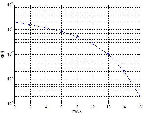
BER of 64-QAM OFDM in AWGN

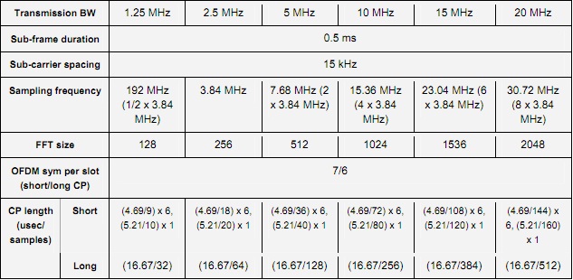
64-QAM is an important component of the LTE Air Interface that promises higher data rates and spectral efficiencies. Combined with OFDM and MIMO it successfully combats the detrimental effects of the wireless channels and provides data rates in excess of 100Mbps (peak data rate). Here, we discuss a simple example of 64-QAM modulation with OFDM in an AWGN channel. We assume a bandwidth of 1.25MHz which corresponds to an FFT size of 128.

LTE Bandwidth
LTE Bandwidth

Given below is the code for this scheme.

%%%%%%%%%%%%%%%%%%%%%%%%%%%%%%%%%%%%%%%%%%%%%%%%%%%%%%%%%%
% FUNCTION TO CALCULATE BER OF 64-QAM OFDM IN AWGN
% n_bits: Input, number of bits
% n_fft: Input, FFT size 
% EbNodB: Input, energy per bit to noise PSD
% ber: Output, bit error rate
% Copyright RAYmaps (www.raymaps.com)
%%%%%%%%%%%%%%%%%%%%%%%%%%%%%%%%%%%%%%%%%%%%%%%%%%%%%%%%%%
function[ber]= M_QAM(n_bits,n_fft,EbNodB);
Eb=7;
M=64;
k=log2(M);
EbNo=10^(EbNodB/10);
x=transpose(round(rand(1,n_bits)));
h1=modem.qammod(M);
h1.inputtype='bit';
h1.symbolorder='gray';
y=modulate(h1,x);
n_sym=length(y)/n_fft;
s_ofdm=zeros(1,n_fft);
r_ofdm=zeros(1,n_fft);
for n=1:n_sym;
s_ofdm=sqrt(n_fft)*ifft(y((n-1)*n_fft+1:n*n_fft),n_fft);
wn=randn(1,n_fft)+j*randn(1,n_fft);
r_ofdm=s_ofdm+sqrt(Eb/(2*EbNo))*wn.';
s_est((n-1)*n_fft+1:n*n_fft)=fft(r_ofdm,n_fft)/sqrt(n_fft);
end
h2=modem.qamdemod(M);
h2.outputtype='bit';
h2.symbolorder='gray';
h2.decisiontype='hard decision';
z=demodulate(h2,s_est.');
ber=(n_bits-sum(x==z))/n_bits;
return
%%%%%%%%%%%%%%%%%%%%%%%%%%%%%%%%%%%%%%%%%%%%%%%%%%%%%%%%%%

As discussed previously, with proper normalization of IFFT and FFT operations the performance of OFDM in AWGN is the same as the performance of the underlying modulation scheme. We have not even introduced the cyclic prefix in our simulation because without a fading channel there is no ISI and cyclic prefix (CP) is of no use. We will introduce the CP when we turn our attention to fading channels.

OFDM 64-QAM
OFDM 64-QAM

It must be noted that although IFFT and FFT are linear inverses of each other proper normalization is required to maintain the signal levels at the transmitter and receiver.

Bit Error Rate of 64-QAM in AWGN

64-QAM is an important modulation scheme being used in WiMAX and LTE. It allows for transmission of 6 bits symbol which results in higher bit rate and spectral efficiency. The calculation of bit error rate of 64-QAM is a bit tricky as there are many different formulas available with varying degrees of accuracy. Here, we first calculate the bit error rate (BER) of 64-QAM using a simulation and then compare it to the theoretical curve for 64-QAM.

%%%%%%%%%%%%%%%%%%%%%%%%%%%%%%%%%%%%%%%%%%%%%%%%%%%%%%
% FUNCTION TO CALCULATE 64-QAM BER USING SIMULATION
% n_bits: Input, number of bits
% EbNodB: Input, energy per bit to noise PSD
% ber: Output, bit error rate
% Copyright RAYmaps (www.raymaps.com)
%%%%%%%%%%%%%%%%%%%%%%%%%%%%%%%%%%%%%%%%%%%%%%%%%%%%%%
function[ber]= M_QAM(n_bits,EbNodB);
M=64;
k=log2(M)
EbNo=10^(EbNodB/10);
x=transpose(round(rand(1,n_bits)));
h1=modem.qammod(M);
h1.inputtype='bit';
h1.symbolorder='gray';
y=modulate(h1,x);
n=randn(1,n_bits/k)+j*randn(1,n_bits/k);
y=y+sqrt(7/(2*EbNo))*n.';
h2=modem.qamdemod(M)
h2.outputtype='bit';
h2.symbolorder='gray';
h2.decisiontype='hard decision';
z=demodulate(h2,y);
ber=(n_bits-sum(x==z))/n_bits
return
%%%%%%%%%%%%%%%%%%%%%%%%%%%%%%%%%%%%%%%%%%%%%%%%%%%%%%
%%%%%%%%%%%%%%%%%%%%%%%%%%%%%%%%%%%%%%%%%%%%%%%%%
% CALCULATE 64-QAM BER USING FORMULA
%%%%%%%%%%%%%%%%%%%%%%%%%%%%%%%%%%%%%%%%%%%%%%%%%
EbNodB=0:2:16;
EbNo=10.^(EbNodB/10);
k=6;
M=64;
x=sqrt(3*k*EbNo/(M-1));
Pb=(4/k)*(1-1/sqrt(M))*(1/2)*erfc(x/sqrt(2));
semilogy(EbNodB,Pb)
%%%%%%%%%%%%%%%%%%%%%%%%%%%%%%%%%%%%%%%%%%%%%%%%%

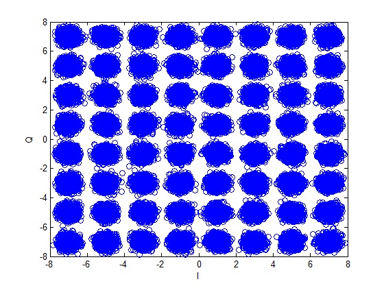
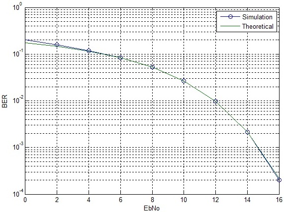
Using the above functions the BER of 64-QAM is calculated as shown below. Also shown is the constellation diagram of 64-QAM after addition of noise.

64-QAM Constellation

64-QAM BER
64-QAM BER

It is observed that the theoretical curve almost overlaps the simulation results. There is only a very small difference at very low signal to noise ratio. The BER of 64-QAM at 16dB is approximately equal to the BER for QPSK at 8dB. Therefore the 64-QAM can only be used in scenarios where there is a very good signal to noise ratio.

In this post we have used built in MATLAB functions for modulation and demodulation. In future posts we try to build up the simulation without using these functions!

OFDM Modulation and Demodulation (AWGN) – II

We have previously looked at a simple OFDM modulation and demodulation scheme. We saw that the BER performance of OFDM in AWGN was the same as the BER performance of the underlying modulation scheme (QPSK in this case). We will now continuously improve upon our basic simulation to get a more realistic picture. In this regard we introduce the cyclic prefix which is used in OFDM to overcome Intersymbol Interference. The duration of the cyclic prefix is 0.8usec (16 samples at 20MHz) resulting in a symbol duration of 4usec (IEEE 802.11a). Given below is the code for OFDM modulation and demodulation with cyclic prefix.

%%%%%%%%%%%%%%%%%%%%%%%%%%%%%%%%%%%%%%%%%%%%%%%%%%%%%%%%%%
% FUNCTION TO CALCULATE BER OF OFDM IN AWGN
% seq_len: Input, number of OFDM symbols
% n_carr: Input, number of subcarriers 
% EbNo: Input, energy per bit to noise PSD
% ber: Output, bit error rate
% Copyright RAYmaps (www.raymaps.com)
%%%%%%%%%%%%%%%%%%%%%%%%%%%%%%%%%%%%%%%%%%%%%%%%%%%%%%%%%%
function[ber]=OFDM_err(seq_len,n_carr,EbNo)
n_pre=16;                                                             
n_tot=n_carr+n_pre;                                                   
for n=1:seq_len
si=2*(round(rand(1,n_carr))-0.5);                                     
sq=2*(round(rand(1,n_carr))-0.5);                                              
s=si+j*sq;                                                            
s_ofdm=sqrt(n_carr)*ifft(s,n_carr);                                   
s_cyc=sqrt(n_carr/n_tot)*([s_ofdm(49:64),s_ofdm]);                    
wn=(1/sqrt(2*10^(EbNo/10)))*(randn(1,n_tot)+j*randn(1,n_tot));        
r=s_cyc+wn;                                                           
r_ext=r(17:80);                                                       
s_est=fft(r_ext,n_carr);                                              
si_est=sign(real(s_est));                                             
sq_est=sign(imag(s_est));                                             
ber1(n)=(n_carr-sum(si==si_est))/n_carr;                              
ber2(n)=(n_carr-sum(sq==sq_est))/n_carr;                               
end
ber=mean([ber1 ber2]);                                                
return
%%%%%%%%%%%%%%%%%%%%%%%%%%%%%%%%%%%%%%%%%%%%%%%%%%%%%%%%%%

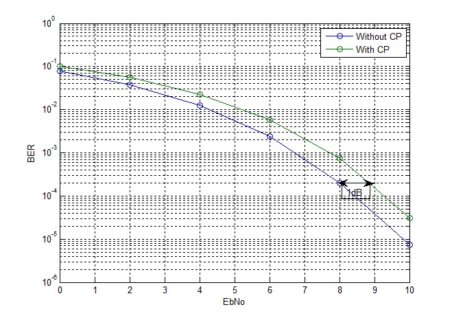
Since the number of samples is increased from 64 to 80 their is an increase in symbol energy. Therefore the signal level needs to be scaled by a factor of sqrt(64/80) to keep the total symbol energy to be the same. This results in approximately 1dB of loss in BER performance as shown in the figure below.

OFDM BER

OFDM Modulation and Demodulation (AWGN)

OFDM modulation works on the principle of converting a serial symbol stream to a parallel symbol stream with each symbol from the parallel set modulating a seperate carrier. The spacing between the carriers is 1/T where T is the duration of the OFDM symbols (without cyclic prefix). This guarantees orthogonality of the carriers i.e. there is no interference between carriers. The addition of orthogonal carriers modulated by parallel symbol streams is equivalent to taking the IFFT of the parallel symbol set. At the receiver the inverse operation of FFT is performed and the parallel symbol streams are converted to serial symbol streams.

The main advantage of this scheme is that one carrier (or set of carriers) may undergo severe fading but other carriers would be able to carry data. Equalization on these narrowband channels is also much easier than equalization of one wideband channel. Intersymbol Interference (ISI) which effects the signal in the time domain is removed by adding a guard period between symbols, called cyclic prefix (which we will discuss later).

OFDM Modulator Demodulator

We demonstrate the performance of OFDM with QPSK modulation in a simple AWGN channel. Although the true benefits of OFDM are really visible when we have a fading channel but this simple example would serve as a good starting point.

%%%%%%%%%%%%%%%%%%%%%%%%%%%%%%%%%%%%%%%%%%%%%%%%%%%%%%%%%%
% FUNCTION TO CALCULATE BER OF OFDM IN AWGN
% seq_len: Input, number of OFDM symbols
% n_carr: Input, number of subcarriers 
% EbNo: Input, energy per bit to noise PSD
% ber: Output, bit error rate
% Copyright RAYmaps (www.raymaps.com)
%%%%%%%%%%%%%%%%%%%%%%%%%%%%%%%%%%%%%%%%%%%%%%%%%%%%%%%%%%
function[ber]=OFDM_err(seq_len,n_carr,EbNo)
for n=1:seq_len
si=2*(round(rand(1,n_carr))-0.5);
sq=2*(round(rand(1,n_carr))-0.5);
s=si+j*sq;
s_ofdm=sqrt(n_carr)*ifft(s,n_carr);
wn=(1/sqrt(2*10^(EbNo/10)))*(randn(1,n_carr)+j*randn(1,n_carr));
r=s_ofdm+wn;
s_est=fft(r,n_carr);
si_est=sign(real(s_est));
sq_est=sign(imag(s_est));
ber1(n)=(n_carr-sum(si==si_est))/n_carr;
ber2(n)=(n_carr-sum(sq==sq_est))/n_carr;
end
ber=mean([ber1 ber2]);                                                           
return
%%%%%%%%%%%%%%%%%%%%%%%%%%%%%%%%%%%%%%%%%%%%%%%%%%%%%%%%%

OFDM BER AWGN

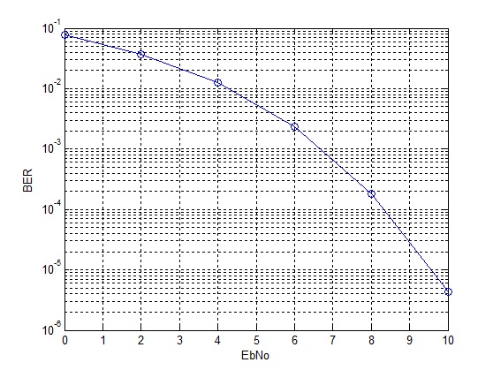
As expected in an AWGN channel the BER performance of OFDM is simply the BER performance of QPSK in AWGN. With cyclic prefix, some of the transmitted energy would be wasted and the BER performance would be a bit worse (to be discussed in future posts).

Alamouti Scheme

So we have seen that multiple transmit antennas provide the same gain as multiple receive antennas if the channel state information can be fed back to the transmitter. But what if the channel state information cannot be fed back to the transmitter (or it can be done but not quickly enough). The solution to this problem is the so called “Alamouti Scheme”. In this scheme two symbols are simultaneously transmitted from two transmit antennas and in the next time slot phase shifted versions of these two symbols are transmitted over the two transmit antennas. The channel is assumed to be quasi static i.e. it is static over the duration of two time slots but then changes for the next two time slots. A combining scheme is used at the receiver which separates the two symbols.

%%%%%%%%%%%%%%%%%%%%%%%%%%%%%%%%%%%%%%%%%%%%%%%%%%%%%%%
% l: Length of symbol sequence
% EbNo: Energy per bit to noise power spectral density
% ber: Output bit error rate
% Copyright www.raymaps.com
%%%%%%%%%%%%%%%%%%%%%%%%%%%%%%%%%%%%%%%%%%%%%%%%%%%%%%%

function[ber]=err_rate7(l,EbNo)
s1i=2*(round(rand(1,l))-0.5);
s1q=2*(round(rand(1,l))-0.5);
s1=s1i+j*s1q;
s2i=2*(round(rand(1,l))-0.5);
s2q=2*(round(rand(1,l))-0.5);
s2=s2i+j*s2q;

n1=(1/sqrt(2*10^(EbNo/10)))*(randn(1,l)+j*randn(1,l));
n2=(1/sqrt(2*10^(EbNo/10)))*(randn(1,l)+j*randn(1,l));
h1=(1/sqrt(2))*((randn(1,l))+j*(randn(1,l)));
h2=(1/sqrt(2))*((randn(1,l))+j*(randn(1,l)));

r1=h1.*(sqrt(1/2)*s1)+h2.*(sqrt(1/2)*s2)+n1;
r2=-h1.*conj(sqrt(1/2)*s2)+h2.*conj(sqrt(1/2)*s1)+n2;
s1_=conj(h1).*r1+h2.*conj(r2);
s2_=conj(h2).*r1-h1.*conj(r2);
s1i_=sign(real(s1_));
s1q_=sign(imag(s1_));

ber1=(l-sum(s1i==s1i_))/l;
ber2=(l-sum(s1q==s1q_))/l;
ber=mean([ber1 ber2]);
return
%%%%%%%%%%%%%%%%%%%%%%%%%%%%%%%%%%%%%%%%%%%%%%%%%%%%%%%

Alamouti Scheme

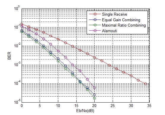
It is observed that this scheme is 3dB worse than MRC (and transmit diversity with CSI). This reason for this is that unlike MRC the signals are transmitted from two transmit antennas thus the power is halved at each transmit antenna (this scheme is also 3dB worse than transmit diversity with CSI at transmitter because although both schemes transmit half the power from each source but in this scheme the noise power is doubled due to the combining scheme working over two time slots).