The mmWave Channel
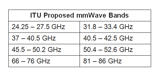
It is well known that wireless signals at millimeter wave frequencies (mmWave) suffer from high path loss, which limits their range. In particular there are higher diffraction and penetration losses which makes reflected and scattered signals to be all the more important. Typical penetration losses for building materials vary from a few dBs to more than 40 dBs [1]. There is also absorption by the atmosphere which increases with frequency. But there are also some favorable bands where atmospheric losses are low (<1dB/km).
Path Loss and Friis Equation
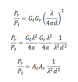
But what about Line of Sight (LOS) communication, which might be an important scenario for small cells with radii less than a 100 meters. If there is a direct path between the transmitter and receiver do we still get a high path loss (ignoring atmospheric absorption at the moment)? The most fundamental relationship between the transmit and receive power is given by Friis Equation, which is given below. Here Pt is the transmit power, Pr is the receive power, d is the transmit-receive separation, λ is the wavelength and Gt and Gr are the transmit and receive antenna gains respectively.
Role of Antenna Aperture
As shown above we can re-write this equation in terms of the antenna aperture at the transmitter and receiver, At and Ar respectively. We see that if At and Ar are held constant the receive power as given by Friis equation increases with decreasing wavelength. In fact there is a squared relationship i.e. if wavelength decreases by a factor of 10, receive power increases by a factor of 100. So the question that needs to be asked is how can At and Ar be held constant.
We see that At and Ar are directly proportional to the gain of the antenna and to the squared of the wavelength. So if wavelength decreases by a factor of 10, At and Ar would each decrease by a factor of 100. However we can maintain the value of At and Ar by increasing the gain of the antenna. This can be done by using a single high gain antenna (20 dB or higher gain) or multiple antennas with low to medium gain.
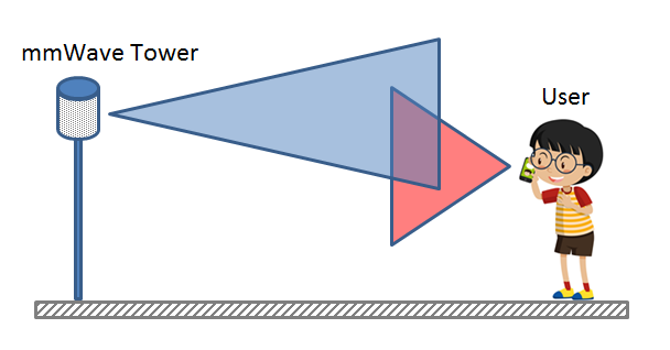
Beamforming is the Solution
Let us consider the extreme case of Isotropic antennas with a gain of unity. One solution is to have a 10 x 10 rectangular grid of such antennas giving us a broadside gain of 100 (20 dB). Placing 100 antennas at the base station might not be a problem at millimeter wave frequencies since the dimensions of the array are directly proportional to the wavelength. For example at 30 GHz with half wavelength separation between antenna elements the dimensions of a 10 x 10 rectangular array would be approximately 5.0 cm x 5.0 cm. Looking at this example it seems that placement of such an array is possible even on a mobile device. In reality, a gain of 20 dB can be achieved by much smaller number of antennas (even a simple patch antenna has a gain of 6 to 9 dB).
Note:
- Measurements at 38 GHz found a penetration loss of nearly 25 dB for a tinted glass window and 37 dB for a glass door. Measurements at 28 GHz showed that outdoor tinted glass and brick pillars had penetration losses of 40.1 dB and 28.3 dB, respectively, but indoor clear glass and drywall only had 3.6 dB and 6.8 dB of loss [1].
- Only 7 dB/km of attenuation is expected due to heavy rainfall rates of 1 inch/hr for cellular propagation at 28 GHz, which translates to only 1.4 dB of attenuation over 200 m distance [2].
- The probability of availability of LOS channel increases with decrease in transmit-receive separation. In an Urban Macrocell (UMa) environment at 100 m separation the probability is 0.35 to 0.40 but this increases to 0.90 at 25 m separation [1].
- There are four international organizations that are working on developing path loss models for mmWave. These include 3rd Generation Partnership Project (3GPP), 5G Channel Model (5GCM), Mobile and wireless communications Enablers for the Twenty-twenty Information Society (METIS) and Millimeter-Wave based Mobile Radio Access Network for Fifth Generation Integrated Communications (mmMAGIC) [1].
[1] T. S. Rappaport, Y. Xing, G. R. MacCartney, Jr., A. F. Molisch, E. Mellios, J. Zhang, “Overview of Millimeter Wave Communications for Fifth-Generation (5G) Wireless Networks-with a focus on Propagation Models,” in IEEE Transactions on Antennas and Propagation, Special Issue on 5G, Nov. 2017.
[2] T. S. Rappaport et al., “Millimeter Wave Mobile Communications for 5G Cellular: It Will Work!” IEEE Access, vol. 1, pp. 335–349, May 2013.