We have previously discussed the bit error rate (BER) performance of M-QAM in AWGN. We now discuss the BER performance of M-QAM in Rayleigh fading. The one-tap Rayleigh fading channel is generated from two orthogonal Gaussian random variables with variance of 0.5 each. The complex random channel coefficient so generated has an amplitude which is Rayleigh distributed and a phase which is uniformly distributed. As usual the fading channel introduces a multiplicative effect whereas the AWGN is additive.
The function “QAM_fading” has three inputs, ‘n_bits’, ‘M’, ‘EbNodB’ and one output ‘ber’. The inputs are the number of bits to be passed through the channel, the alphabet size and the Energy per Bit to Noise Power Spectral Density in dB respectively whereas the output is the bit error rate (BER).
%%%%%%%%%%%%%%%%%%%%%%%%%%%%%%%%%%%%%%%%%%%%%%%%%%%%%%%%%%%%%%%%%%
% FUNCTION THAT CALCULATES THE BER OF M-QAM IN RAYLEIGH FADING
% n_bits: Input, number of bits
% M: Input, constellation size
% EbNodB: Input, energy per bit to noise power spectral density
% ber: Output, bit error rate
% Copyright RAYmaps (www.raymaps.com)
%%%%%%%%%%%%%%%%%%%%%%%%%%%%%%%%%%%%%%%%%%%%%%%%%%%%%%%%%%%%%%%%%%
function[ber]= QAM_fading(n_bits, M, EbNodB)
% Transmitter
k=log2(M);
EbNo=10^(EbNodB/10);
x=transpose(round(rand(1,n_bits)));
h1=modem.qammod(M);
h1.inputtype='bit';
h1.symbolorder='gray';
y=modulate(h1,x);

% Channel
Eb=mean((abs(y)).^2)/k;
sigma=sqrt(Eb/(2*EbNo));
w=sigma*(randn(n_bits/k,1)+1i*randn(n_bits/k,1));
h=(1/sqrt(2))*(randn(n_bits/k,1)+1i*randn(n_bits/k,1));
r=h.*y+w;

% Receiver
r=r./h;
h2=modem.qamdemod(M);
h2.outputtype='bit';
h2.symbolorder='gray';
h2.decisiontype='hard decision';
z=demodulate(h2,r);
ber=(n_bits-sum(x==z))/n_bits
return
%%%%%%%%%%%%%%%%%%%%%%%%%%%%%%%%%%%%%%%%%%%%%%%%%%%%%%%%%%%%%%%%%%

The bit error rates of four modulation schemes 4-QAM, 16-QAM, 64-QAM and 256-QAM are shown in the figure above. All modulation schemes use Gray coding which gives a few dB of margin in the BER performance. As with the AWGN case each additional bit per symbol requires about 1.5-2 dB in signal to ratio to achieve the same BER.
Although not shown here similar behavior is observed for higher order modulation schemes such as 1024-QAM and 4096-QAM (the gap in the signal to noise ratio for the same BER is increased to about 5dB).
Lastly we explain some of the terms used above.
Rayleigh Fading
Rayleigh Fading is a commonly used term in simulation of Digital Communication Systems but it tends to differ in meaning in different contexts. The term Rayleigh Fading as used above means a single tap channel that varies from one symbol to the next. It has an amplitude which is Rayleigh distributed and a phase which is Uniformly distributed. A single tap channel means that it does not introduce any Inter Symbol Interference (ISI). Such a channel is also referred to as a Flat Fading Channel. The channel can also be referred to as a Fast Fading Channel since each symbol experiences a new channel state which is independent of its previous state (also termed as uncorrelated).
Gray Coding
When using QAM modulation, each QAM symbol represents 2,3,4 or higher number of bits. That means that when a symbol error occurs a number of bits are reversed. Now a good way to do the bit-to-symbol assignment is to do it in a way such that no neighboring symbols differ by more than one bit e.g. in 16-QAM, a symbol that represents a binary word 1101 is surrounded by four symbols representing 0101, 1100, 1001 and 1111. So if a symbol error is made, only one bit would be in error. However, one must note that this is true only in good signal conditions. When the SNR is low (noise has a higher magnitude) the symbol might be displaced to a location that is not adjacent and we might get higher number of bits in error.
Hard Decision
The concept of hard decision decoding is important when talking about channel coding, which we have not used in the above simulation. However, we will briefly explain it here. Hard decision is based on what is called “Hamming Distance” whereas soft decision is based on what it called “Euclidean Distance”. Hamming Distance is the distance of a code word in binary form, such as 011 differs from 010 and 001 by 1. Whereas the Euclidean distance is the distance before a decision is made that a bit is zero or one. So if the received sequence is 0.1 0.6 0.7 we get a Euclidean distance of 0.8124 from 010 and 0.6782 from 001. So we cannot make a hard decision about which sequence was transmitted based on the received sequence of 011. But based on the soft metrics we can make a decision that 001 was the most likely sequence that was transmitted (assuming that 010 and 001 were the only possible transmitted sequences).
Author: Yasir
More than 20 years of experience in various organizations in Pakistan, the USA, and Europe. Worked with the Mobile and Portable Radio Group (MPRG) of Virginia Tech and Qualcomm USA and was one of the first researchers to propose Space Time Block Codes for eight transmit antennas. Have publsihed a book “Recipes for Communication and Signal Processing” through Springer Nature.
40 thoughts on “M-QAM Bit Error Rate in Rayleigh Fading”
Hi Sir,
I am a bit confused as to what the r./h does as the step before is just multiplying by h. What kind of equalization does this perform?
For a flat fading channel i.e. a channel whose response does not change with frequency, equalization can be performed by simple division. This is the same principle used in equalization of individual subcarriers in OFDM.
Hello Sir,
Nice explanation, but I have been trying to imitate that in the below conditions. Please can you explain how to go about this
Simulation Setting:
Sending Signal:16QAM
Transmission channel: H(z)= 1.30 + 0.05z-1 + 0.34z-2 – 0.03z-3 + 0.40z-4
SNR:15dB,20dB,25dB
Data length:5000
Requirements:
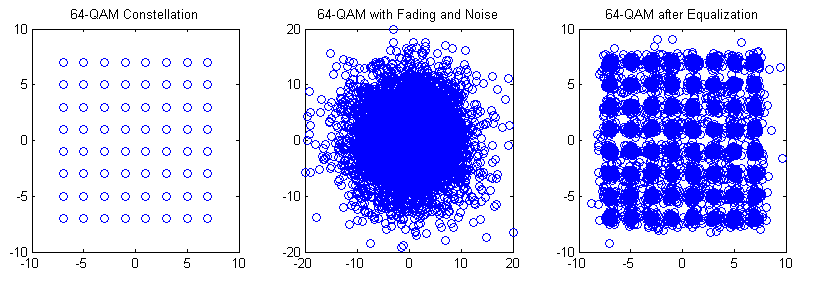
Plot and compare the constellation of the sending signal, received signal and equalized signal under different SNR conditions.
Hi Peter,
That’s an excellent question. I am posting two pieces of code that would help you understand the changes you need to make to the above code. The first one uses BPSK modulation (real signal) whereas the second one uses QPSK modulation (complex signal). The second one is more pertinent to the problem at hand as 16-QAM modulation is just an extension of QPSK modulation. Hope this helps.
YA
%%%%% BPSK Modulation %%%%% clear all close all symbols=5; Ns=20; Eb=1; EbNo=10; s=([ones(1,Ns)]')*([1,-1,1,-1,1]); s=s(:); s=transpose(s); plot(s);hold on h=[1.30,0.05,0.34,-0.03,0.40]; r=conv(s,h); sigma=sqrt(Eb/(2*EbNo)); r=r+sigma*randn(1,length(r)); plot(r(1:symbols*Ns),'r') [s_est, R]=deconv(r,h); plot(s_est,'g');hold off xlabel('Sample Number') ylabel('Signal Level') legend('Tx','Rx','Eq')%%%%% QPSK Modulation %%%%% clear all close all symbols=5; Ns=20; Eb=1; EbNo=10; s=([ones(1,Ns)]')*([1+i,-1+i,-1-i,1-i,1+i]); s=s(:); s=transpose(s); plot(s,'bo-');hold on h=[1.30,0.05,0.34,-0.03,0.40]; r=conv(s,h); sigma=sqrt(Eb/(2*EbNo)); r=r+sigma*(randn(1,length(r))+i*randn(1,length(r))); plot(r(1:symbols*Ns),'r*') [s_est,R]=deconv(r,h); plot(s_est,'g+');hold off xlabel('In-phase') ylabel('Quadrature') legend('Tx','Rx','Eq')i found the formula ber in 16qam as (3/8)*erfc(sqrt(4/10)*snr)).
what is the formula of ber for 16qam in rayleigh channel?
Please look at the following link. It gives exact as well as approximate formula:
http://www.raymaps.com/index.php/theoretical-ber-of-m-qam-in-rayleigh-fading/
I need full program to calculate BER QAM in rayleigh fading and gaussian noise..
Look at the code for the wrapper file I posted below. The above code with the wrapper file generates the BER curves.
Hope this helps!
Hello,
plz I need matlab code showing the difference between MQAM and QPSK in terms of BER in matlab , could you help me
Thanks,
This might be helpful (4-QAM = QPSK).
http://www.raymaps.com/index.php/m-qam-bit-error-rate-in-rayleigh-fading/
John
How to compare BER versus Eb/No on 64-QAM coderate 2/3 with 64-QAM coderate 1/2? I need the syntax. Thanks
Putri
Thank you, this is very helpful. Do you have a tutorial to calculate the BER vs Eb/No in Rician channel?
Putri
Unfortunately at this moment I don’t. I hope to post something on this soon.
John
Rician channel is nothing but Rayleigh channel with a dominant LOS component. You can simulate this by adding a constant term to the complex channel coefficient. Greater the value of the constant term stronger the LOS component and lower the BER.
Consider two Gaussian random variables X and Y. Here X models the specular component (LOS) and Y models the random/scatter component. X has non-zero mean m, Y has zero mean and both have equal variance σ2. Then the transformation, Z=(X2+Y2)1/2 is Rician Distributed.
Ref: Gaussianwaves.com
Hope this helps.
Please help sir, whats the meaning of n in this program?
clear all;
close all;
M=4;
k=log2(M);
l=k*1e5;
EbNodB=0:2:24;

for n=1:length(EbNodB);n
ber(n)=QAM_fading(l,M,EbNodB(n));
end

semilogy(EbNodB,ber,'o-');
grid on
xlabel('EbNo (dB)')
ylabel('BER')
I need full program to calculate BER QAM in rayleigh fading. Thanks.
n is the number of points in the EbNodB vs BER plot. You need to first save the code given above in an m-file as QAM_fading.m and then run this wrapper program. The m-file QAM_fading.m will be called for each value of EbNodB and will return the value of BER for each value of EbNodB. Hope this helps.
John
Hi, I just wanna thank u for the provided scripts and also for really helpful website. Thanx
Dear Odai,
I left that to you. So you can also learn to program yourself. But if you are having problems you can use the code below.
%%%%%%%%%%%%%%%%%%%%%%%%%%%%%%%%%%%
clear all;
close all;
M=4;
k=log2(M);
l=k*1e5;
EbNodB=0:2:24;

for n=1:length(EbNodB);n
    ber(n)=QAM_fading(l,M,EbNodB(n));
end

semilogy(EbNodB,ber,'o-');
grid on
xlabel('EbNo (dB)')
ylabel('BER')
%%%%%%%%%%%%%%%%%%%%%%%%%%%%%%%%%%%
John
Hello, I need full code for plot the result for different M
Please see the wrapper code above.
Dear John,
I have a question with your code at the receiver.
% Receiver
r=r./h;
You should know h coefficient before dividing r=r./h. So could you please help to describe how can we obtain/estimate h by using pilot symbol?
Thank you so much.
Tony
Dear Tony,
That is a very good question. Indeed the channel coefficient ‘h’ must be known for it to be compensated at the receiver. If you transmitted pilot symbol ‘s_p’ at the transmitter you would receive x = h*s_p+w at the receiver. Dividing ‘x’ by the known pilot symbol you can get an estimate of the channel i.e. h_est = x/s_p = h+(w/s_p). Hope this makes sense.
John
Sir, can you please give me the expression for error probability of M-QAM in Rayleigh fading channel by using Moment Generating method, and compare the result with the expression derived naturally… i.e., by direct integration by parts. And also a matlab program to simulate the results & check that they matches..!!
Hi Mr John,
I am trying to simulate Symbol Error Rate for 16QAM (in Rayleigh fading channel).
I am having difficulties with the simulation. I tried using Simulink to simulate but failed.
What should I do then?
To Mr John
Greeting,
Nice to know you. I’m interested in a research about performance of wimax downlink over haps channel in terms of capacity/ packet error rate (PER) vs HAP elevation angle. I’m still confused about that. Could you please provide some matlab scripts related to this topic. I look forward to your help.
thanks!
Oooops…
I confused with BPSK performance….sorry.
Thanks for your plentiful and valuable information about digital communications. But I guess you may check the Rayleigh channel gain “h” because something strange with the plot. According to the theoretical calculation of 16-QAM BER over Rayleigh , BER = (1/2)*(1-sqrt(rm./(1+rm))) where rm is linear scale Eb/N0, the plot should be start from almost neat to 10^-1 at Eb/No 0dB. It means that the h=randn(n_bits/k,1)+1i*randn(n_bits/k,1). Could you check it again ?
I am student in communication engineering department in Egypt in Arab Academy for Science in Alexandria. I need change type of modulation from BPSK to PAM. Can you help me in change modulation from BPSK to PAM.
Please look at the following post for 4-PAM simulation:
https://www.raymaps.com/index.php/pulse-amplitude-modulation-symbol-error-rate-in-awgn/
http://code.google.com/p/qam-ofdm/downloads/detail?name=M_QAM_OFDM_fading.m
and what is the difference with this code?
It is the same code that I posted there.
What do you mean with this ? n_bits=k*1e5 ?? k is in the function. how can i call it with this value?
You are not changing the value of k which is equal to log2(M). You are just defining the number of bits to be passed through the channel, which must be divisible by k so that you can get a whole number for the number of symbols to be passed through the channel.
The answer will be a number, correct? the ber, how to make the graphic that you show here for the ber?
You need to create a “for loop” for different values of EbNodB and store the ber for each EbNodB. You can then plot these using “semilogy”.
Set n_bits=k*1e5, M=64, EbNodB=30.
Hello,
What are the values of n_bits, M, EbNodB that you used to get those results?
I have (64,64,30) and I get this error:
[ber]= QAM_fading(64, 64, 30)
??? Error using ==> modem.abstractMod.checkModInputSizeBit at 13
Number of elements in each channel of input X must be an integer multiple of log2(M).
Error in ==> modem.abstractMod.modulate_Bit at 11
checkModInputSizeBit(h, x);
Error in ==> modem.abstractMod.modulate at 13
y = feval(h.ProcessFunction, h, x);
Error in ==> QAM_fading at 10
y=modulate(h1,x);
Thank you
Marina