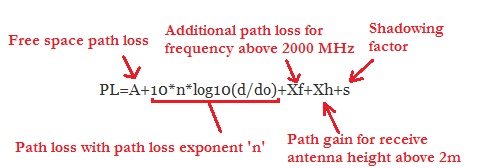
Calculation of the path loss is fundamental to Wireless System Design. There are many models available for calculating the path loss such as Okumura Model, Hata Model, COST-231 Model and more recently the SUI (Stanford University Interim) Model. The SUI Model has been specifically proposed for Broadband Wireless Access Systems such as WiMAX. It defines three types of environments namely A, B and C which are equivalent to the urban, suburban and rural environments defined in the earlier models. According to this model the path loss can be calculated as:
PL=A+10*n*log10(d/do)+Xf+Xh+s
where
n=a-(b*hb)+(c/hb)
A=20*log10(4*pi*do/lambda)
Xf=6.0*log10(f/2000)
Xh=-10.8*log10(hr/2) for A&B
Xh=-20.0*log10(hr/2) for C
and
frequency of operation = f = >2000MHz
transmit receive separation = d = 100 m to 8000 m
reference distance = do = 100 m
base station antenna height = hb = 10 m to 80 m
receive antenna height = h = 2 m to 10 m
shadowing factor with lognormal distribution = s = 8.2 dB to 10.6 dB
The values for the parameters a,b and c for the three environment are given in the table below.

Doing a quick calculation for f=2500 MHz, hb=30 m, hr=2 m, s=8.2, do=100 m and d=1000 m gives us a path loss 137.13 dB for Type-A channel. Increasing the frequency to 3500 MHz (another WiMAX band) increases the path loss to 140.93 dB i.e. there is a 3.8 dB increase in the path loss.
So to recap the path loss given by the SUI model is composed of 5 elements:

1. The free space path loss (A) up to the reference distance of ‘do’.
2. Additional path loss for distance ‘d’ with path loss exponent ‘n’.
3. Additional path loss (Xf) for frequencies above 2000 MHz.
4. Path gain (Xh) for receive antenna heights greater than 2 m.
5. Shadowing factor (s).
Author: Yasir
More than 20 years of experience in various organizations in Pakistan, the USA, and Europe. Worked with the Mobile and Portable Radio Group (MPRG) of Virginia Tech and Qualcomm USA and was one of the first researchers to propose Space Time Block Codes for eight transmit antennas. Have publsihed a book “Recipes for Communication and Signal Processing” through Springer Nature.
2 thoughts on “WiMAX Path Loss Calculation”
Is there any formula in which path loss relates with Electric Field and Frequency?
The Power Density can be calculated from Electric Field Intensity as S=E*E/Zo. The Received Power can then be calculated by multiplying Power Density by Effective Area of the Receive Antenna.