Tag Archives: Path Loss

LTE Path Loss at 700 MHz

In the previous post we had compared the path loss of LTE at 728 MHz and 1805 MHz in a free space line of sight channel. This is a very simplistic channel model which tells us that ratio of the received signal strengths at these frequencies can be simply found as:

(f1/f2)^2=(1805/728)^2=6.15

That is the received signal strength at 728 MHz is 6.15 times higher than the received signal strength at 1805 MHz.

Now let us consider a more realistic channel model known as the COST-231 model. According to this model the path loss (difference between the transmit power and receive power) is given as:

L=46.3+33.9*log10(f)-13.82*log(ht)-a+(44.9-6.55*log10(ht))*log10(d)+C

where

f=frequency in MHz (0.1500 MHz – 2000 MHz)

ht=base station antenna height in m (30 m – 200 m)

hr=mobile station antenna height in m (1 m – 10 m)

d=transmit receive separation in km (1 km – 20 km)

C=3 dB for metropolitan centres

and mobile station antenna correction factor is given as:

a=3.2*log10(11.75*hr)^2-4.97

Using the above equations with ht=30 m, hr=1 m and d=1 km the path loss at 728 MHz and 1805 MHz is found out to be 100.63 dB and 114.00 dB respectively i.e. there is a gain of 13.37 dB when using the lower frequency. In simpler terms the received signal at 728 MHz would be 21.72 times stronger than the signal at 1805 MHz.

Such a remarkable improvement in signal strength or in signal to noise ratio (SNR) has the potential of increasing the throughput four folds. For example at an SNR of 1.5 dB QPSK 1/2 would give a throughput of 6.00Mbps whereas at an SNR of 14.7 dB a modulation coding scheme (MCS) of 64QAM 2/3 would result in a throughput of 24.01 Mbps.
Modulation Coding Schemes

Propagation and In-Building Penetration at 700MHz

It is quite well known that wireless signals travel further at lower frequencies. This phenomenon has become particularly important in the context of LTE where a frequency band has been allocated at 700MHz. We would like to quantify the benefits that can be achieved by using this frequency band.

Firstly we find the received signal power at 728 MHz (lowest downlink frequency) and at 3600 MHz (highest downlink frequency) in a free space line of sight channel. The transmit power is set to 1 W and omnidirectional antennas are considered at the transmitter and receiver. The received power for these two frequencies at a distance of 1000 m is found out to be -59.68dBm and -73.57dBm respectively i.e. there is a gain of 13.88 dB by using the lower frequency band. In simpler terms the signal power would be more than 20 times stronger at the lower frequency. This result can also be simply obtained by taking the square of the ratio the two frequencies.

(3600/728)^2 = 24.45

Similarly compared to a frequency of 1805 MHz, the signal at 728 MHz would be more than 6 times stronger.

(1805/728)^2 = 6.1474

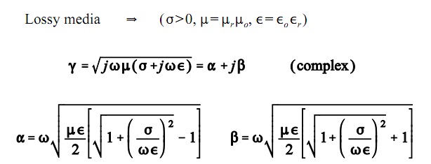
Now we turn our attention to the penetration loss i.e. how much would the signal attenuate when passing through a concrete wall. For this we would have to calculate the attenuation constant (alpha) which is given as:

Attenuation Constant
Propagation Constant

Alpha, the attenuation constant is the real part of the propagation constant gamma whereas Beta, the phase constant, is the imaginary part. These quantities depend upon the frequency, relative permittivity, relative permeability and conductivity of the material. The penetration loss can then be found as -20*log10(exp(-alpha*thickness)). Using the properties of concrete the penetration loss at 728 MHz and at 1805 MHz is found out to be 4.16 dB and 10.38 dB i.e. there is a gain of 6.22 dB when using the lower frequency. In simpler terms the signal at the lower frequency would be more than 4 times stronger. We have considered a concrete wall of 10 cm thickness.

It is quite evident that the frequency of operation plays a big role in determining the propagation loss and the penetration loss. The frequency band of 728-746 MHz would thus be a prized commodity and operators would be willing to pay handsome amount to secure it.

Note:

1. We have ignored the reflection that occurs at the interface as its effect is comparably quite small.

2. Following were the material properties of concrete used in the calculation for penetration loss.

728 MHz
Relative permittivity = 4.5775
Relative permeability = 1.0000
Conductivity = 0.055

1805 MHz
Relative permittivity = 4.1000
Relative permeability = 1.0000
Conductivity = 0.1300