
Wireless researchers are continuously exploring ways to increase the spectral efficiency (bits/sec/Hz) and energy efficiency (bits/Joule) of wireless communication systems [1]. Spectral efficiency can generally be improved by using larger constellations or by using multiple antennas at the transmitter and receiver, better known as MIMO. But increasing energy efficiency is not that straightforward. Let’s consider this in bit more detail.
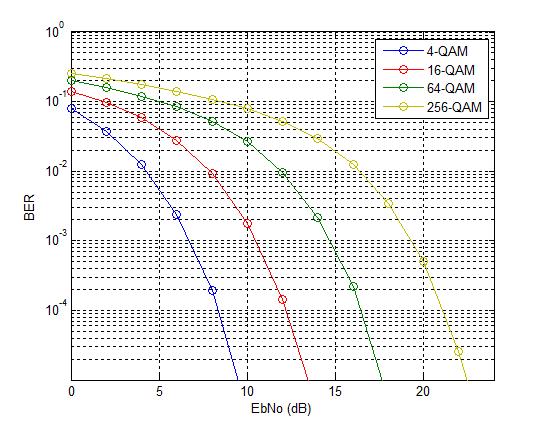
If the constellation size is increased, we may be able to send more bits through the channel for a given bandwidth but the Bit Error Rate (BER) would deteriorate as minimum distance between constellation points decreases. To get the same BER we would have to bump up the transmit power (or energy). Let’s look at the example below. Let’s assume that we move from QPSK (2 bits per symbol) to 16-QAM (4 bits per symbol) i.e. we double the data rate. In an AWGN environment we would need 4dB of additional energy to achieve the same BER (similar results for fading environment). So, we have not gained anything in terms of energy efficiency.
Now let’s consider the case of multiple antennas. Multiple antennas at the transmitter or receiver means multiple RF chains which are power hungry. In particular, simultaneous transmission from multiple transmit antennas means more power consumption [1]. In addition to power consumption in the RF front-end there might also be higher power consumption at the baseband at the receiver side since more complex signal processing is required to separate the signals. Specifically, brute force methods such as Maximum Likelihood (ML) are quite power hungry.
A relatively new technique to improve the spectral efficiency and the energy efficiency of wireless communication system is called Index Modulation (IM) [2]. There are two main types of IM, one that uses multiple transmit antennas (Spatial Modulation) and one that uses multiple carriers (OFDM-IM). We will focus here on Spatial Modulation also known as SM.
As previously discussed, having multiple RF chains at the transmitter increases the energy consumption. What if we can use single RF chain with multiple transmit antennas i.e., we use multiplexing. This has two advantages. An obvious one is that energy consumption is reduced at the transmitter end. A not so obvious one is that, by selecting which antenna to transmit from, there is implicit exchange of information between transmitter and receiver.
Let’s assume that we have four antennas and we transmit from only one during a symbol period then we can transmit two bits by this simple selection scheme, assuming that receiver can detect that which transmit antenna was used. The total number of bits transmitted is then given as log2(nT) + log2(M). Where nT is the number of transmit antennas and M is the constellation size. A slightly more complex variant of this scheme is where we select a subset of transmit antennas for each symbol duration. This has the potential to further improve the spectral efficiency of the system at the cost of energy efficiency.
An Illustrative Example
Let’s assume that we have BPSK modulation and there are two transmit antennas. For each symbol period we either transmit a +1 or -1 from antenna Tx-1 or Tx-2. The channel gain from Tx-1 to the receiver is 0.50 and channel gain from Tx-2 to the receiver is 0.25 (we assume these gains are static and known at the receiver). So, during any given symbol period the received signal could be -0.50, -0.25, 0.25 or 0.50. That is, we have expanded the signal constellation from 2 to 4. Let’s assume that we receive -0.50 at the receiver. This means that a -1 was transmitted from Tx-1. Similarly, if we receive -0.25 it means that a -1 was transmitted from Tx-2 and so on. Tx-1 or Tx-2 or for that matter any number of antennas could be selected based upon a lookup table at the transmitter side. Tx-1 could be selected when the input is -1 (or binary 0) and Tx-2 could be selected when input is +1 (or binary 1).
Applying the formula, we discussed above, number of transmitted bits can be calculated as:
log2(nT) + log2(M)= log2(2) + log2(2)=1+1=2 bits/time slot
A last point about antenna correlation. Assume that the transmit antennas are closely spaced and the channel coefficients are 0.25 and 0.30 respectively. Then the expanded constellation points would be much closer together and the probability of error increases!
References
[1] Jing Jiang, Mehrdad Dianati, Muhammad Ali Imran, Rahim Tafazolli, and Yan Chen, “On the Relation Between Energy Efficiency and Spectral Efficiency of Multiple-Antenna Systems,” IEEE Transactions on Vehicular Technology, 2013.
[2] Ertugrul Basar, “Index Modulation Techniques for 5G Wireless Networks,” IEEE Communications Magazine, 2016.
4 thoughts on “Index Modulation Explained”
Hi John,
Can you provide some basic MATLAB code for Index modulation with an energy detector?
Thank you in advance
I do not have a piece of code on this topic, at the moment. Can you share a bit more detail about what you want, maybe someone else has worked on it.
YA
We have a multitone signal (for example 2 tones), then how we can transmit and receive information using the tone-index modulation concept.
Can provide any hint on how we can do this in Matlab?
Thank you
Look at the example in the post.