Category Archives: Antennas

Uniform linear array, rectangular array, circular array and MIMO.

Some Common Antenna Radiation Patterns

A Radiation Pattern is a 3 dimensional description of how an antenna radiates power in the surrounding space. This pattern is usually measured at a sufficient distance from the antenna known as the far-field. In simple words it is the power radiated in a certain direction with reference to an omni-directional antenna (a theoretical antenna that radiates   equally in all the directions). Given below are the radiation patterns for some common antenna types.

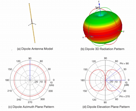
Dipole Antenna 3D Radiation Pattern
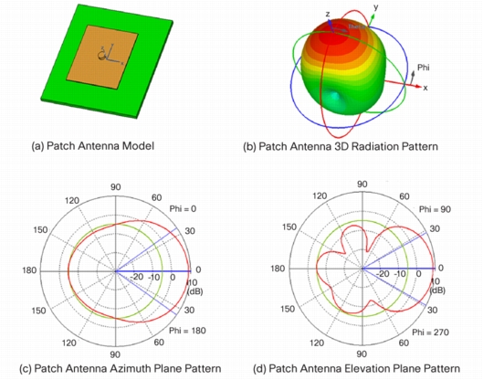
Patch Antenna 3D Radiation Pattern
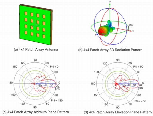
4x4 Patch Array 3D Radiation Pattern
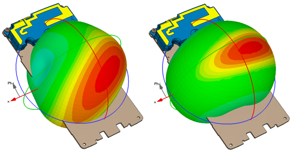
GSM Band Antenna Radiation Patterns from a Cell Phone
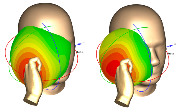
GSM Band Antenna Radiation Pattern from a Cell Phone in Presence of Head and Hand
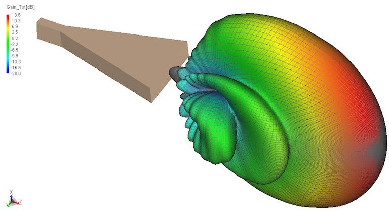
Horn Antenna Radiation Pattern
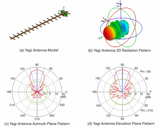
Yagi Antenna 3D Radiation Pattern
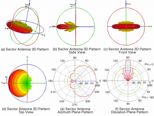
Sector Antenna 3D Radiation Pattern
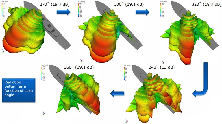
Radar Antenna Radiation Patterns

Although the Radiation Pattern is a 3 dimensional quantity it is usually sufficient to describe it in two orthogonal planes (one horizontal and one vertical) as shown in the figures above.

References:

[1] Cisco Aironet Antennas and Accessories: Antenna Patterns and Their Meaning

Antenna Gain and Directivity

Antenna Gain and Directivity are two terms that are sometimes not that well understood. The Antenna Gain and Directivity are related through the following equation.

G(θ,φ)=E*D(θ,φ)

That is, the Antenna Gain in a particular direction is equal to the Directivity in that direction multiplied by the Antenna Efficiency. Antenna Directivity is the ratio of energy transmitted (or received) by the antenna in a particular direction to the energy transmitted (or received) in that direction by an isotropic source. This is also known as the Directive Gain.

The Antenna Gain (also known as the Power Gain) seems to be a better metric to quantify the performance of an antenna as it takes into account the efficiency in converting electrical energy supplied to the antenna into radiated energy.

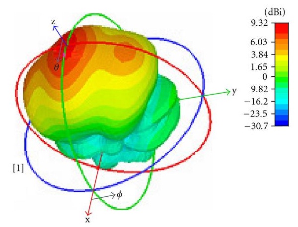
The 3-dimensional plot of the Gain of an antenna is known as the radiation pattern. The Antenna Gain with reference to an isotropic source is given in dBi (decibel above isotropic source). Sometimes the Antenna Gain is given with reference to a Dipole Antenna and is labelled as dBd. The figure below shows the Directivity of a Patch Antenna embedded inside a human body [1].

Directivity of a Patch Antenna

Note:

1. An isotropic source (a source that radiates uniformly in all directions) is only a theoretical concept and does not exist in reality.

2. The sun can be considered an isotropic radiator since it radiates uniformly in all directions (almost).

3. When no direction is given the Gain refers to the maximum Gain.

Reference:

[1] http://www.hindawi.com/journals/ijap/2008/167980/

E-field of a Dipole Antenna

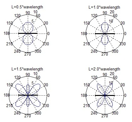
In the previous post we plotted the E-field of a half wave dipole. We now turn our attention to higher antenna lengths such 1,1.5 and 2.0 times the wavelength. The E-field pattern is a three dimensional pattern, however, we only plot the E-field in a 2D plane along the axis of the dipole.

E-field of a Dipole
E-field of a Dipole

It is observed that as the antenna length is increased from 0.5*wavelength to 1.0*wavelength the antenna becomes more directional. However, as the length is further increased from 1.0*wavelength to 1.5*wavelength and 2.0*wavelength sidelobes begun to appear. These sidelobes are an unwanted phenomenon in a typical telecommunications application. When the antenna is placed vertically (shown horizontal in the above figure) it radiates uniformly along a horizontal plane and would provide coverage within a circular cell (not for 2.0*wavelength where there is no radiation at 90 degrees).

Half Wave Dipole Antenna

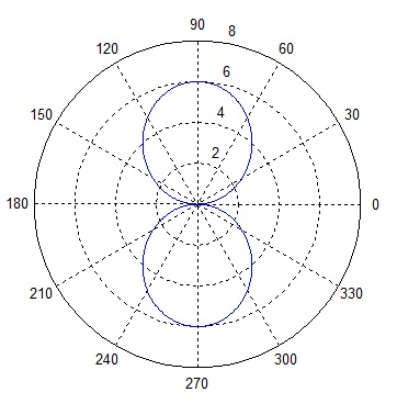
A dipole antenna is a simple antenna that can be built out of electrical wire. The most common dipole antenna is a half wave dipole which is constructed from a piece of wire half wavelength long. The wire is split in the center to connect the feeding wires. The E-field of the antenna has a circular pattern along a plane which cuts the axis of the antenna perpendicularly and is similar to a figure of 8 in a plane along the axis of the antenna [3D pattern]. The exact E-field can be calculated as:

Expression for E-field of a Dipole Antenna
E-field Pattern of a Dipole Antenna

The MATLAB code for generating the above pattern is given below.

n=377;
Io=1;
r=10;
lambda=0.3;
k=(2*pi)/lambda;
L=lambda/2;

theta=0:0.01:2*pi;
E=j*n*Io*exp(-j*k*r)*(1/(2*pi*r))*((cos(k*L*cos(theta)/2)-cos(k*L/2))./sin(theta));
polar(theta, abs(E))

Note that the above is true within an area at a sufficient distance from the antenna known as the far-field of the antenna. Closer to the antenna i.e. in the near-field the E-field expression is a bit more complex.

Antenna Radiation Pattern and Antenna Tilt

An introductory text in Communication Theory would tell you that antennas radiate uniformly in all directions and the power received at a given distance ‘d’ is proportional to 1/(d)^2. Such an antenna is called an isotropic radiator. However, real world antennas are not isotropic radiators. They transmit energy in only those directions where it is needed. The Gain of a antenna is defined as the ratio of the power transmitted (or received) in a given direction to the power transmitted in that direction by an isotropic source and is expressed in dBi.

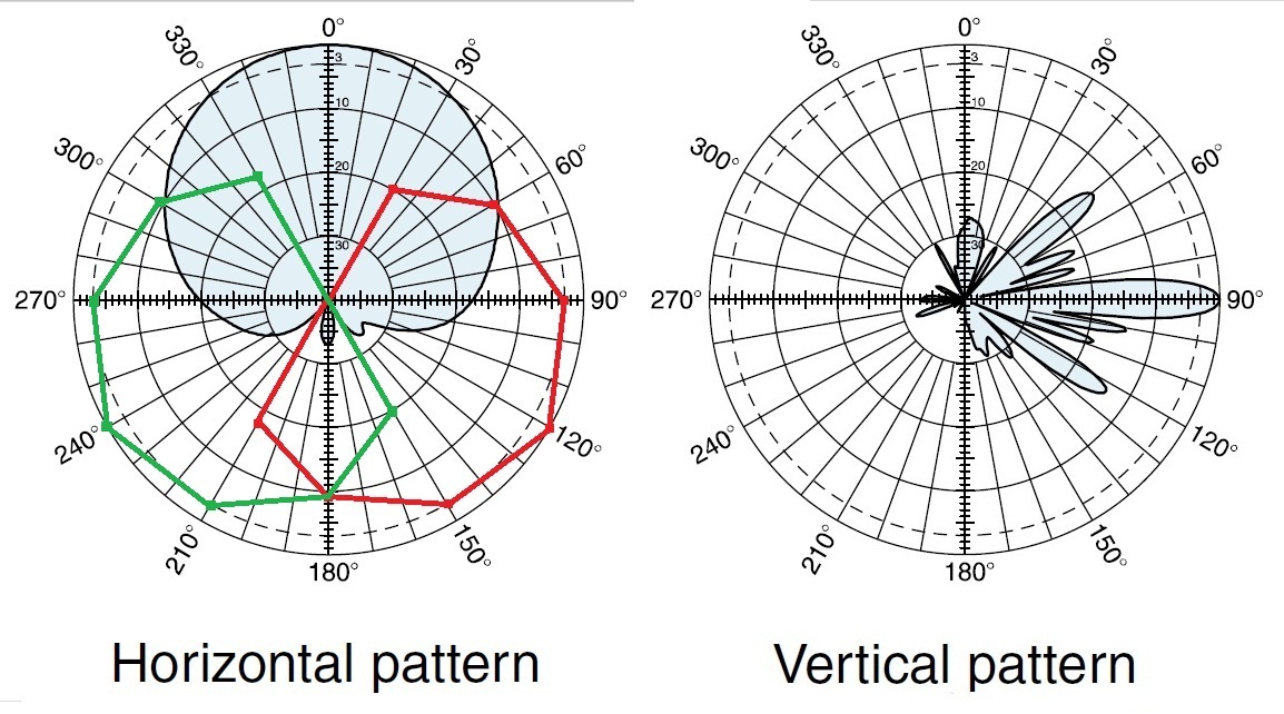
Although antenna Gain is a three dimensional quantity, the Gain is usually given along horizontal and vertical planes passing through the center of the antenna. The Horizontal and Vertical Gain patterns for a popular base station antenna Kathrein 742215 are shown in the figure below.

Kathrein 742215 Gain Pattern

The actual Gain is given with respect to the maximum Gain which is a function of the frequency e.g. in the 1710-1880 MHz band the maximum Gain has a value of 17.7dBi. Another important parameter is the Half Power Beam Width (HPBW) which has values of 68 degree and 7.1 degree in the horizontal and vertical planes respectively. HPBW is defined as the angle in degrees within which the power level is equal to or above the -3 dB level of the maximum.

Also shown in the above figure are approximate Horizontal Gain patterns for two antennas that have been rotated at 120 degrees and 240 degrees. Together these three antennas cover the region defined as a cell. There would obviously be lesser coverage in areas around the intersection of two beams.

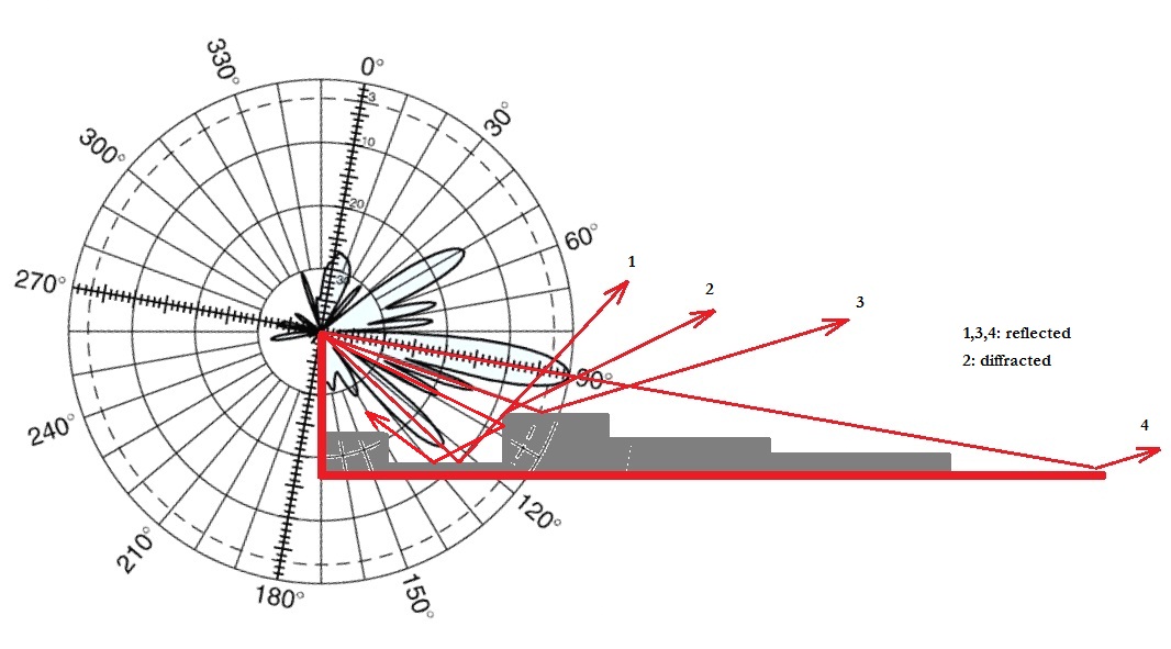
A somewhat more interesting pattern is in the vertical direction where the HPBW is only 7.1 degrees. Thus it is very important to direct this beam in the right direction. A perfectly horizontal beam would result in a large cell radius but may also result in weak signal areas around the base station. A solution to this problem is to give a small tilt to the antenna in the downward direction, usually 5-10 degrees. This would reduce the cell radius but allow for a more uniform distribution of energy within the cell. In reality the signal from the main beam and side lobes (one significant side lobe around -15 dB) would bounce off the ground and buildings around the cell site and spread the signal around the cell.

Antenna Tilt of 10 Degrees

The above figure gives a 2D view of signal propagation from an elevated antenna with a downward tilt of 10 degrees in an urban environment.

Base Station Antenna Tilt and Path Loss

Path loss is basically the difference in transmit and receive powers of a wireless communication link. In a Free Space Line of Sight (LOS) channel the path loss is defined as:

L=20*log10(4*pi*d/lambda)

where ‘d’ is the transmit receive separation and ‘lambda’ is the wavelength. It is also possible to include the antenna gains in the link budget calculation to find the end to end path loss (cable and connector losses may also be factored in). Antenna gains are usually defined along a horizontal plane and vertical plane passing through the center of the antenna. The antenna gain can then be calculated at any angle in 3D using the gains in these two planes.

Although 3D antenna gains are quite complex quantities simplified models are usually used in simulations e.g. a popular antenna Kathrein 742215 has the following antenna gain models [1] along the horizontal and vertical planes:

Gh(phi)=-min(12*(phi/HPBWh)^2, FBRh)+Gm

Gv(theta)=max(-12*((theta-theta_tilt)/HPBWv)^2, SLLv)

where

Gm=18 dBi
HPBWh=65 degrees
HPBWv=6.2 degrees
SLLv=-18 dB

We are particularly interested in the gain in the vertical plane and the effect of base station antenna tilt on the path loss. We assume that the mobile antenna station has uniform gain in all directions. The path loss can be then calculated as:

L=20*log10(4*pi*d/lambda)+Gv(theta)+Gh(phi)

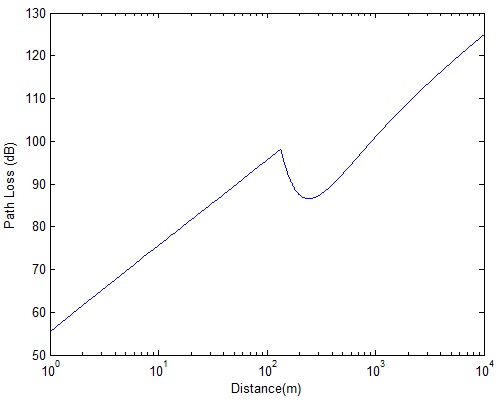
where we have assumed that Gh(phi)=0 for all phi (this is a reasonable simplification since changing the distance along the line of sight would not change Gh(phi) ). Using the above expression the path loss in free space is calculated for a frequency of 1805 MHz, base station antenna height of 30 m and an antenna tilt of 5 degrees.
Effect of Antenna Tilt on Path Loss

It is observed that there is a sudden decrease in path loss at distances where the antenna main beam is directed. If the antenna tilt is increased this behavior would be observed at smaller distances. Since we have used a side lobe level that is fixed at -18 dB we see a rapid change in behavior at around 100 m. If a more realistic antenna model is used we would see a gradual decrease in path loss at this critical distance.

[1] Fredrik Gunnarsson, Martin N Johansson, Anders Furuskär, Magnus Lundevall, Arne Simonsson, Claes Tidestav, Mats Blomgren, “Downtilted Base Station Antennas – A Simulation Model Proposal and Impact on HSPA and LTE Performance”,
Ericsson Research, Ericsson AB, Sweden. Presented at VTC 2008.