Tag Archives: Antenna

E and H Field of a Patch

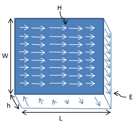
The Electric and Magnetic Field variations within a patch are sometimes a bit confusing and difficult to visualize. The figure below shows the E and H Field variations within a rectangular patch of length L and width W.

E and H Field of a Patch

As can be seen the E-field varies along the length of the patch with minimum at the centre and maximum at the edges (maximum positive and maximum negative). The H-field also varies along the length is in a direction perpendicular to the E-field. The H-field is maximum at the center and minimum at the edges. Thus the impedance is zero at the center of the patch (using Z=V/I).

Another point to note is that the E-field does not completely terminate at the edges along the length of the antenna rather it extends at the outer periphery. These field extensions are known as fringing fields and cause the patch to radiate [1].

[1] http://www.orbanmicrowave.com/The_Basics_Of_Patch_Antennas.pdf

Patch Antenna Design using Transmission Line Model

A microstrip antenna can be designed using either the transmission line model or the cavity model (more complex models also exist that suit a particular design). We here demonstrate the transmission line model since it is fairly simple to implement and results in antenna designs with reasonably good performance in terms of return loss and efficiency.

Patch Antenna Construction

The design starts with selecting the operating frequency, selecting a substrate with the required permittivity, and defining the width of the substrate. Thick substrates with low permittivity result in antenna designs with high efficiency and large bandwidths. Thin substrates with high permittivity lead to a smaller antenna size but with a lower bandwidth and a high-radiation loss. The tradeoffs between substrate thickness and permittivity and antenna bandwidth and efficiency have been discussed in the literature.

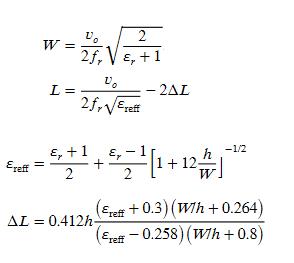
According to the transmission line model, the length L and width W of the patch are calculated as

 Although the design of the patch is quite simple, the design of the feeding mechanism is not that straightforward. There are four possible methods that can be used:

(1) Microstrip-line feed

(2) Probe feed

(3) Aperture-coupled feed

(4) Proximity-coupled feed

Reference

[1] Yasir Ahmed, Yang Hao, and Clive Parini, “A 31.5 GHz Patch Antenna Design for Medical Implants,” International Journal of Antennas and Propagation, vol. 2008, Article ID 167980, 6 pages, 2008.

E-field of a Patch Antenna

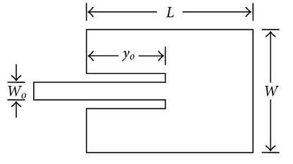
A Microstrip Patch Antenna or simply a Patch Antenna is a very common antenna type used in cell phones and many other electronic devices. It basically consists of two metallic plates separated by a dielectric layer. The metallic plates are usually made of copper or some other highly conductive material. Another important feature of this antenna is the feeding mechanism, which is also made of a highly conductive material. A Microstrip Patch Antenna fed by a 50 ohm transmission line and a quarterwave transformer is shown below.

Patch Antenna Construction

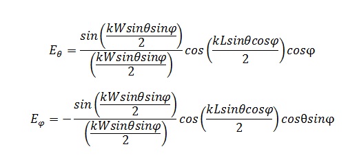
The E-field and H-field generated by the Patch Antenna can be calculated by using a simulation tool such as CST Microwave Studio. It is dependent on the length ‘L’ and width ‘W’ of the patch as well as on the wavelength ‘λ’ and the feeding mechanism. Other important parameters are the width of the substrate and the permittivity of the substrate. The E-field can be approximated as.

E-field of a Patch Antenna

Part of the above equations is a sinc function which can be calculated by the MATLAB sinc function.

References:

[1] http://www.emtalk.com/mwt_mpa.htm

[2] http://www.antenna-theory.com/antennas/patches/antenna.php#introduction

Some Commonly Used Antenna Terminology

Antenna Pattern

Antenna Pattern or Radiation Pattern is a three dimensional description of how the antenna radiates energy in to the space around it. All practical antennas are directional i.e. they radiate more energy in certain directions and lesser energy in other directions. Although the Radiation Pattern is a three dimensional quantity it can be described in two perpendicular planes known as the principal planes. Usually one of these planes is horizontal (azimuth plane) and the other is vertical (elevation plane).

Gain

As discussed previously antennas do not radiate uniformly in all directions. Antenna Gain is the ratio of the power transmitted in a certain direction to the power transmitted in that direction by an isotropic source. An isotropic source is an imaginary source which radiates power uniformly in all directions. The Antenna Gain is usually given in units of decibels and is given as dBi (dB above an isotropic source). The Antenna Gain may also be given with reference to a Dipole Antenna and this is labelled as dBd. When no direction is specified Antenna Gain refers to the maximum Gain.

3-dB Beamwidth

The 3-dB Beamwidth is the angle between two points on the main lobe of the antenna that are 3dB down from the maximum value. A smaller Beamwidth means that an antenna is more directional and a higher Beamwidth means that the antenna is less directional. The 3-dB Beamwidth is usually defined in the two principal planes i.e. the azimuth plane and elevation plane.

Front-to-back ratio

The front to back ration (F/B) is the ratio of the Gain in the forward direction to the Gain in the backward direction within a principal plane (azimuth or elevation). It is an important metric in certain scenarios where radiation towards the back of the antenna is undesirable e.g. as in 120 degree sectored antennas used in cellular networks. The ratio is usually given on a logarithmic scale and labelled as dB.

Polarization

The polarization of an antenna is a somewhat difficult concept to comprehend. The polarization of an antenna describes the orientation of the E-field that is generated by the antenna. Usually the orientation is horizontal or vertical but it could also be circular for the case where the E-field rotates (clockwise or counter clockwise) as it travels. If a transmit antenna is vertically polarized then the receive antenna should also be vertically polarized to achieve maximum power transfer through the medium.

VSWR

The voltage standing wave ratio (VSWR) is defined as the ratio of the maximum voltage to the minimum voltage in a standing wave pattern. A ratio of 1:1 means that all power was transferred to the antenna and there are no reflections. Typically RF components have 50 or 75 ohms impedance and antennas must have the same impedance to achieve maximum power transfer.

VSWR bandwidth

The VSWR bandwidth is defined as the frequency range over which an antenna has a specified VSWR. Often, the 2:1 VSWR bandwidth is specified, but 1.5:1 is also common.

Omnidirectional antenna

An omnidirectional antenna is an antenna that has a non-directional pattern (circular pattern) in a given plane with a directional pattern in any orthogonal plane. Examples of omnidirectional antennas are dipoles and collinear antennas.

Reference:
[1] Cisco Aironet Antennas and Accessories, Antenna Patterns and Their Meaning.
Some Common Antenna Radiation Patterns

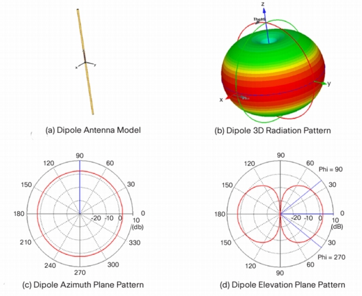
A Radiation Pattern is a 3 dimensional description of how an antenna radiates power in the surrounding space. This pattern is usually measured at a sufficient distance from the antenna known as the far-field. In simple words it is the power radiated in a certain direction with reference to an omni-directional antenna (a theoretical antenna that radiates   equally in all the directions). Given below are the radiation patterns for some common antenna types.

Dipole Antenna 3D Radiation Pattern
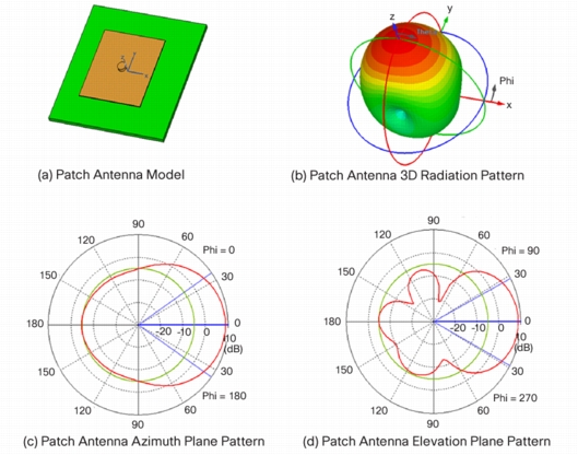
Patch Antenna 3D Radiation Pattern
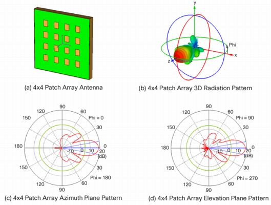
4x4 Patch Array 3D Radiation Pattern
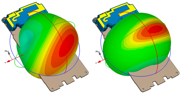
GSM Band Antenna Radiation Patterns from a Cell Phone
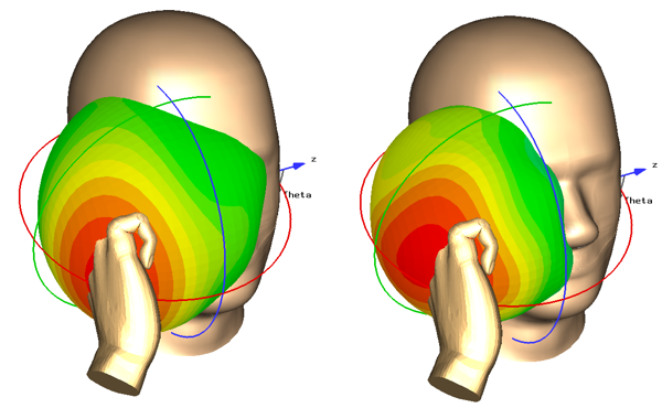
GSM Band Antenna Radiation Pattern from a Cell Phone in Presence of Head and Hand
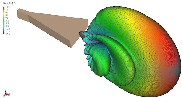
Horn Antenna Radiation Pattern
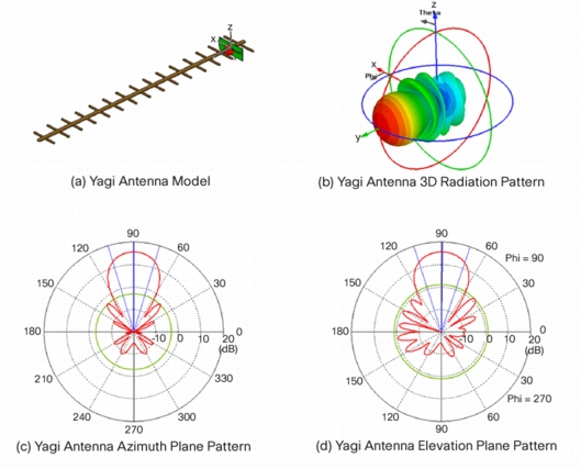
Yagi Antenna 3D Radiation Pattern
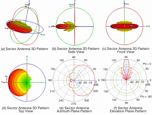
Sector Antenna 3D Radiation Pattern
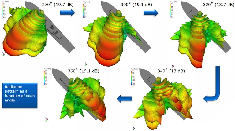
Radar Antenna Radiation Patterns

Although the Radiation Pattern is a 3 dimensional quantity it is usually sufficient to describe it in two orthogonal planes (one horizontal and one vertical) as shown in the figures above.

References:

[1] Cisco Aironet Antennas and Accessories: Antenna Patterns and Their Meaning

Antenna Gain and Directivity

Antenna Gain and Directivity are two terms that are sometimes not that well understood. The Antenna Gain and Directivity are related through the following equation.

G(θ,φ)=E*D(θ,φ)

That is, the Antenna Gain in a particular direction is equal to the Directivity in that direction multiplied by the Antenna Efficiency. Antenna Directivity is the ratio of energy transmitted (or received) by the antenna in a particular direction to the energy transmitted (or received) in that direction by an isotropic source. This is also known as the Directive Gain.

The Antenna Gain (also known as the Power Gain) seems to be a better metric to quantify the performance of an antenna as it takes into account the efficiency in converting electrical energy supplied to the antenna into radiated energy.

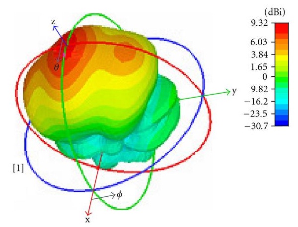
The 3-dimensional plot of the Gain of an antenna is known as the radiation pattern. The Antenna Gain with reference to an isotropic source is given in dBi (decibel above isotropic source). Sometimes the Antenna Gain is given with reference to a Dipole Antenna and is labelled as dBd. The figure below shows the Directivity of a Patch Antenna embedded inside a human body [1].

Directivity of a Patch Antenna

Note:

1. An isotropic source (a source that radiates uniformly in all directions) is only a theoretical concept and does not exist in reality.

2. The sun can be considered an isotropic radiator since it radiates uniformly in all directions (almost).

3. When no direction is given the Gain refers to the maximum Gain.

Reference:

[1] http://www.hindawi.com/journals/ijap/2008/167980/