Tag Archives: RF Planning

Eclipse

Eclipse 1.0 – A Paradigm Shift in RF Planning

NEW: Simulation of a Moving Transmitter (such as a car)

NEW: Simulation of a Moving Transmitter (such as a pedestrian)

Radio frequency planning is an essential component of network planning, roll-out, up-gradation, expansion etc. Several methods can be adopted for this from something as simple as free space models, empirical path loss models to the significantly more complicated, time consuming and expensive drive testing. Drive testing gives very accurate results but these results can be rendered useless by changing the position of an antenna or the tilt or transmit power of an antenna requiring another run in the field. One solution to this problem is ray-tracing which is very accurate but is usually considered to be very computationally expensive and of little practical value. But recent advances in computational power of machines coupled with efficient techniques have given a new lease of life to this method.

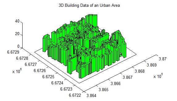
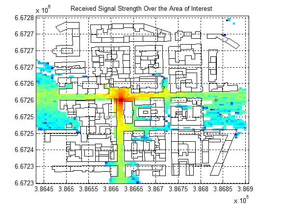
Eclipse is a near real-time simulation software for prediction of signal strength in urban areas. The software uses shooting and bouncing ray (SBR) method of ray tracing with 1 degree ray separation, 1 m step size and 9 interactions per ray path. The simulation parameters can be varied according to the resolution required. The code is highly optimized to give results in shortest possible time. It is especially useful for network planning of ultra-dense wireless networks where a dense network of antennas is placed on lamp posts instead of telecom towers. Various frequency bands can be simulated, along with different antenna radiation patterns and MIMO configurations.


Helsinki 3D Building Data

Received Signal Strength Over Area of Interest

Note: If you would like to run a test simulation send us a request at info@raymaps.com

Android Apps

1. Rx Signal Meter

Received signal strength calculation is required by RF engineers working in the field. This application provides an easy to use interface to calculate the received signal strength. Input parameters include the transmit power, transmit antenna gain, receive antenna gain, transmit receive separation and frequency of operation. Output is the received signal strength in dBm.

https://play.google.com/store/apps/details?id=com.raymaps.path.loss

2. Rx Signal Pro

A simple application that can be used to calculate the Received Signal Strength using one of the following six models.
1. Free Space Path Loss
2. Hata Model
3. COST-231 Model
4. ECC-33 Model
5. Ericsson Model
6. SUI Model
Input parameters include the transmit power, frequency, transmit-receive separation, base station antenna height and mobile station antenna height. Output parameter is the Received Signal Strength in dBm. The application is also available in Desktop version.

https://play.google.com/store/apps/details?id=com.raymaps.signal.me…

3. Path Loss Calculator

A simple application that can be used to calculate the Path Loss using one of the following six models.

1. Free Space Path Loss
2. Hata Model
3. COST-231 Model
4. ECC-33 Model
5. Ericsson Model
6. SUI Model

Input parameters include the frequency, transmit-receive separation, base station antenna height and mobile station antenna height. Output parameter is the Path Loss in dB. The application is also available in Desktop version.

https://play.google.com/store/apps/details?id=com.raymaps.path.loss…

4. RF Planner

This is a simple application which can be used to do RF planning of a GSM, WCDMA, LTE or WiMAX site. The input parameters are the Tx Power, Rx Sensitivity, Tx Height, Rx Height and Frequency of operation. The output parameter is the Cell Radius which is used to plot the coverage area of the cell site on Google Maps. The coverage scenario can be selected from the following three options:
1. Urban
2. Suburban
3. Rural
The underlying model is applicable to Frequencies of up to 3500 MHz, Distances of 100-8000 m, BS Antenna Heights of 10-80 m and MS Antenna Height of 2-10 m.

https://play.google.com/store/apps/details?id=com.raymaps.rf.planner1