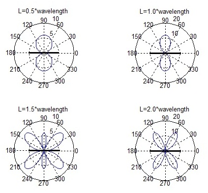
In the previous post we plotted the E-field of a half wave dipole. We now turn our attention to higher antenna lengths such 1,1.5 and 2.0 times the wavelength. The E-field pattern is a three dimensional pattern, however, we only plot the E-field in a 2D plane along the axis of the dipole.

It is observed that as the antenna length is increased from 0.5*wavelength to 1.0*wavelength the antenna becomes more directional. However, as the length is further increased from 1.0*wavelength to 1.5*wavelength and 2.0*wavelength sidelobes begun to appear. These sidelobes are an unwanted phenomenon in a typical telecommunications application. When the antenna is placed vertically (shown horizontal in the above figure) it radiates uniformly along a horizontal plane and would provide coverage within a circular cell (not for 2.0*wavelength where there is no radiation at 90 degrees).
Author: Yasir Ahmed (aka John)
More than 20 years of experience in various organizations in Pakistan, the USA, and Europe. Worked as a Research Assistant within the Mobile and Portable Radio Group (MPRG) of Virginia Tech and was one of the first researchers to propose Space Time Block Codes for eight transmit antennas. The collaboration with MPRG continued even after graduating with an MSEE degree and has resulted in 12 research publications and a book on Wireless Communications. Worked for Qualcomm USA as an Engineer with the key role of performance and conformance testing of UMTS modems. Qualcomm is the inventor of CDMA technology and owns patents critical to the 4G and 5G standards.
-I agree. We have used this type of anetnna on field day with great results. Long wires as well with a tuner, sometimes up only 20-feet.