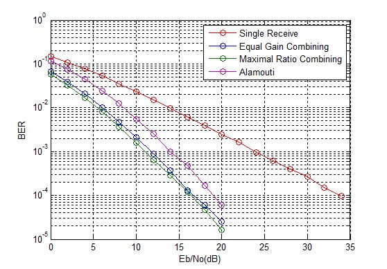
So we have seen that multiple transmit antennas provide the same gain as multiple receive antennas if the channel state information can be fed back to the transmitter. But what if the channel state information cannot be fed back to the transmitter (or it can be done but not quickly enough). The solution to this problem is the so called “Alamouti Scheme”. In this scheme two symbols are simultaneously transmitted from two transmit antennas and in the next time slot phase shifted versions of these two symbols are transmitted over the two transmit antennas. The channel is assumed to be quasi static i.e. it is static over the duration of two time slots but then changes for the next two time slots. A combining scheme is used at the receiver which separates the two symbols.
%%%%%%%%%%%%%%%%%%%%%%%%%%%%%%%%%%%%%%%%%%%%%%%%%%%%%%%
% l: Length of symbol sequence
% EbNo: Energy per bit to noise power spectral density
% ber: Output bit error rate
% Copyright www.raymaps.com
%%%%%%%%%%%%%%%%%%%%%%%%%%%%%%%%%%%%%%%%%%%%%%%%%%%%%%%

function[ber]=err_rate7(l,EbNo)
s1i=2*(round(rand(1,l))-0.5);
s1q=2*(round(rand(1,l))-0.5);
s1=s1i+j*s1q;
s2i=2*(round(rand(1,l))-0.5);
s2q=2*(round(rand(1,l))-0.5);
s2=s2i+j*s2q;

n1=(1/sqrt(2*10^(EbNo/10)))*(randn(1,l)+j*randn(1,l));
n2=(1/sqrt(2*10^(EbNo/10)))*(randn(1,l)+j*randn(1,l));
h1=(1/sqrt(2))*((randn(1,l))+j*(randn(1,l)));
h2=(1/sqrt(2))*((randn(1,l))+j*(randn(1,l)));

r1=h1.*(sqrt(1/2)*s1)+h2.*(sqrt(1/2)*s2)+n1;
r2=-h1.*conj(sqrt(1/2)*s2)+h2.*conj(sqrt(1/2)*s1)+n2;
s1_=conj(h1).*r1+h2.*conj(r2);
s2_=conj(h2).*r1-h1.*conj(r2);
s1i_=sign(real(s1_));
s1q_=sign(imag(s1_));

ber1=(l-sum(s1i==s1i_))/l;
ber2=(l-sum(s1q==s1q_))/l;
ber=mean([ber1 ber2]);
return
%%%%%%%%%%%%%%%%%%%%%%%%%%%%%%%%%%%%%%%%%%%%%%%%%%%%%%%

It is observed that this scheme is 3dB worse than MRC (and transmit diversity with CSI). This reason for this is that unlike MRC the signals are transmitted from two transmit antennas thus the power is halved at each transmit antenna (this scheme is also 3dB worse than transmit diversity with CSI at transmitter because although both schemes transmit half the power from each source but in this scheme the noise power is doubled due to the combining scheme working over two time slots).
Author: Yasir Ahmed (aka John)
More than 20 years of experience in various organizations in Pakistan, the USA, and Europe. Worked as a Research Assistant within the Mobile and Portable Radio Group (MPRG) of Virginia Tech and was one of the first researchers to propose Space Time Block Codes for eight transmit antennas. The collaboration with MPRG continued even after graduating with an MSEE degree and has resulted in 12 research publications and a book on Wireless Communications. Worked for Qualcomm USA as an Engineer with the key role of performance and conformance testing of UMTS modems. Qualcomm is the inventor of CDMA technology and owns patents critical to the 4G and 5G standards.
Raj: What this expression is doing is essentially introducing a phase shift before the transmission such that after passing through the channel the signal has zero phase shift. The expression (conj(h1)./abs(h1)) introduces the phase shift at the Tx and multiplication at the Rx in the expression h1.*sr1 cancels that phase shift. Note we only adjusted the phase and not the amplitude. Hope this makes sense!